
A ball picking robot

A technology of robots and basketball baskets, applied to rackets, balls, loading/unloading, etc., which can solve the problem of getting between the two blades of the first rotating impeller, reducing the picking success rate and picking efficiency, and long picking time of table tennis balls And other problems, to achieve the effect of reducing the number of use and the weight of the whole machine, improving the efficiency of ball picking, and improving the reliability and stability of operation

Active Publication Date: 2021-03-23
CHONGQING VOCATIONAL INST OF ENG
View PDF7 Cites 0 Cited by
  • Summary
  • Abstract
  • Description
  • Claims
  • Application Information

AI Technical Summary

Problems solved by technology

Since the table tennis ball is relatively light and easy to roll, it cannot be guaranteed to enter between the two blades of the first rotating impeller without error
Therefore, during the rotation of the first rotating impeller, only a very small number of ping-pong balls enter between the two blades of the first rotating impeller, and even no ping-pong balls enter between the two blades of the first rotating impeller. Not only will energy be wasted due to the idling of the first rotating impeller, but also there are problems such as a long time for picking up table tennis balls and a low picking-up success rate. One rotating impeller, or by constantly adjusting the position of the robot to change the position of the rotating impeller so that the table tennis ball is within the rotation range of the first rotating impeller. This adjustment process is very tedious and greatly reduces the success rate and efficiency of picking up.

Method used


Image

  • A ball picking robot
  • A ball picking robot
  • A ball picking robot

Examples


Embodiment Construction

[0038] The present invention will be further described below in conjunction with accompanying drawing:

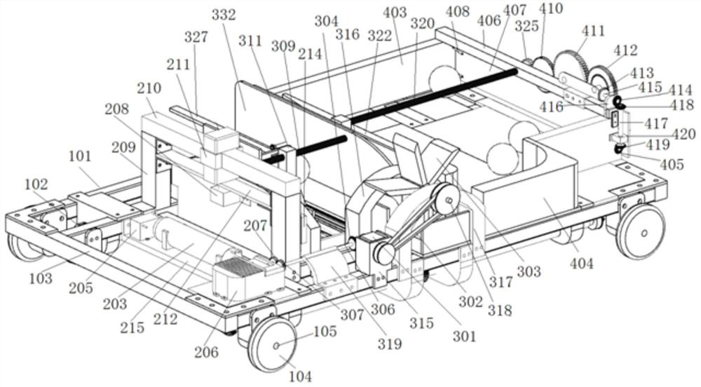
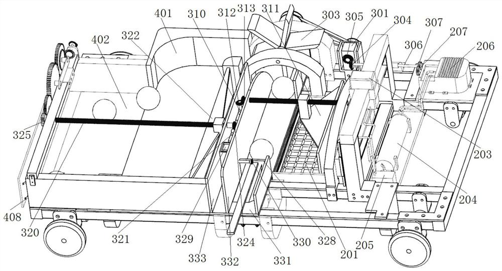
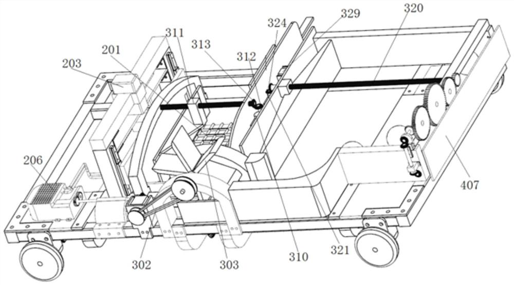
[0039] Such as Figure 1-Figure 6 A ball picking robot shown includes a walking mechanism and a ball picking mechanism, a ball pushing mechanism and a ball storing mechanism installed on the walking mechanism.

[0040] The walking mechanism includes a vehicle frame 101, several wheel assemblies mounted on the vehicle frame 101, and a transmission assembly 2 for driving the wheel assemblies to rotate. The vehicle frame 101 includes an outer frame 102 and auxiliary parts 102 arranged in the outer frame 101 . The vehicle frame 101 is made of steel, which improves the structural strength and plays a stable supporting role for other mechanisms. The wheel assembly includes a wheel 104 , a wheel axle 105 and a gear five sleeved on the wheel axle 105 . Both ends of the wheel axle 105 are fixed on the vehicle frame 101 through a wheel axle bracket 107 respectively, and the wheel ...


PUM


Abstract

The invention relates to a ball picking robot, which comprises a walking mechanism, a ball picking mechanism, a ball pushing mechanism and a ball storing mechanism. The ball picking mechanism includes a ball picking basket, an air cylinder for driving the ball picking basket to move up and down, an air storage tank for providing air source for the cylinder, a solenoid valve arranged at the air outlet of the air storage tank, and a miniature valve connected to the air storage tank. An air pump and a shield assembly arranged at the opening of the rear end of the pick-up basket. Gear one is installed on the input end of micro air pump. The ball pushing mechanism includes a rotating volleyball assembly. The rotary volleyball assembly includes a two-way motor, a rotary impeller connected to the output shaft one of the two-way motor through a belt assembly, a gear two installed on the output shaft two of the two-way motor, and a gear drive connected to the second gear through a gear three installed at one end of the two-way motor. Shaft, the gear four that is installed on the other end of the gear transmission shaft and is meshed with gear one. The invention has the characteristics of simple structure, convenient operation, high picking success rate and picking efficiency.

Description

technical field [0001] The invention relates to the technical field of sports equipment, in particular to a ball picking robot. Background technique [0002] Along with the raising of living standard, ball games such as table tennis, badminton and golf are more and more popular. As everyone knows, when people are playing ball, especially when practicing playing, many balls will be played everywhere. If they are not picked up in time, they will be easily stepped on by players and cause damage to the balls or cause people to fall and get injured. To pick up a large amount of balls scattered on the field, people usually bend over to pick up the balls with their hands or hold a ball picking tool to pick up the balls. Due to the many times of needing to pick up the ball in the daily training process, manually picking up the ball not only wastes time, affects the training efficiency, but also has a greater labor intensity for the people who pick up the ball. [0003] With the ad...

Claims


Application Information

Patent Timeline
Patent Type & Authority Patents(China)
IPC IPC(8): A63B47/02
CPCA63B47/021A63B2047/022A63B2209/14A63B2102/16B65G67/02
Inventor 徐皓贺家顺刘江
Owner CHONGQING VOCATIONAL INST OF ENG
Learn More