Vacuum pump

A technology of vacuum pumps and turbomolecular pumps, applied in pumps, pump components, axial flow pumps, etc., can solve problems such as narrowing of flow paths, degraded exhaust performance, and decreased strength

Active Publication Date: 2020-10-27
EDWARDS JAPAN
View PDF7 Cites 4 Cited by
  • Summary
  • Abstract
  • Description
  • Claims
  • Application Information

AI Technical Summary

Problems solved by technology

If the reaction product accumulates inside the vacuum pump, the flow path of the reaction product may be narrowed and the compression performance and exhaust performance of the vacuum pump may decrease.
On the other hand, if the temperature of the gas transfer part using aluminum, stainless steel, etc. is too high for the rotor blades and fixed blades, the strength of the rotor blades and fixed blades may decrease and breakage may occur during operation.
In addition, the electric motor that rotates the electrical equipment installed in the vacuum pump and the rotor may not exhibit the desired performance when the temperature becomes high.

Method used


Image

  • Vacuum pump
  • Vacuum pump
  • Vacuum pump

Examples


Embodiment

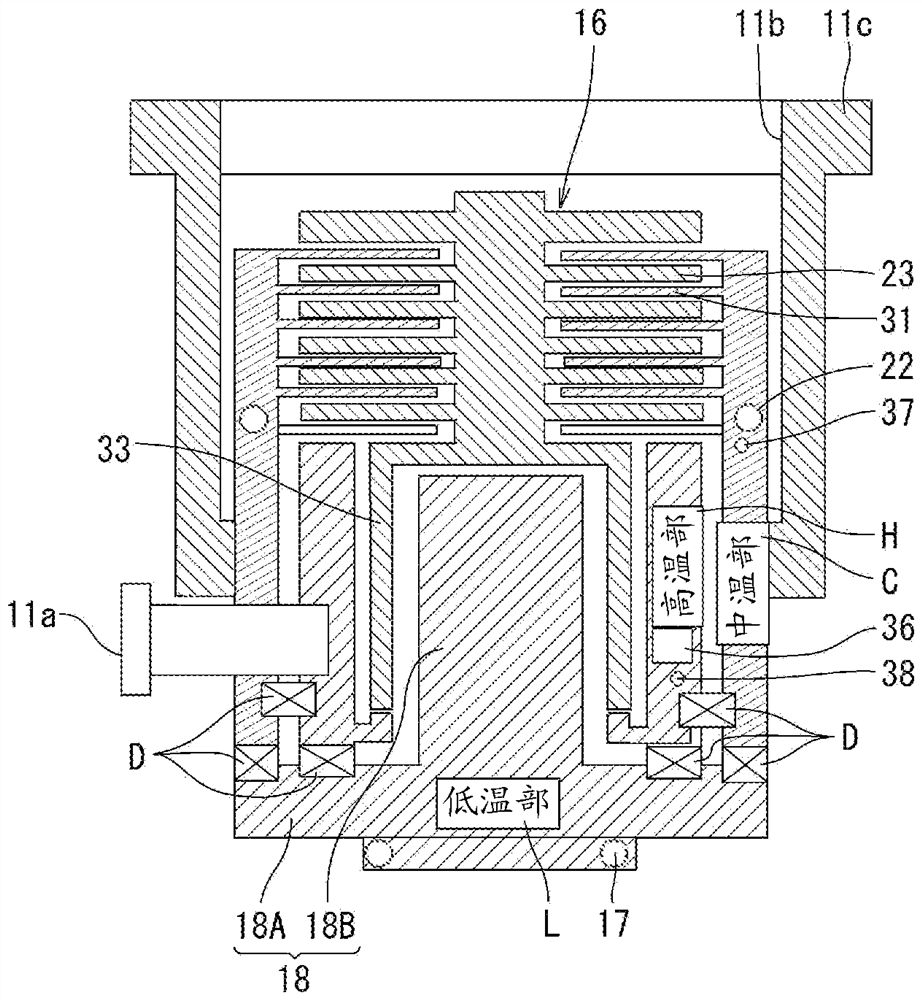
[0045] figure 1 It is a longitudinal sectional view of a vacuum pump 10 shown as an embodiment of the present invention, figure 2 yes figure 1 An enlarged partial cross-sectional view of vacuum pump 10 is shown. figure 1 and figure 2 Herein, the vacuum pump 10 is a compound pump including a turbomolecular pump mechanism PA and a screw groove pump mechanism PB housed in a substantially cylindrical casing 11 as an exhaust function part 12 .

[0046] The vacuum pump 10 has a casing 11, a rotor 15 having a rotor shaft 14 rotatably supported in the casing 11, an electric motor 16 for rotating the rotor shaft 14, and a stator column 18B for accommodating a part of the rotor shaft 14 and the electric motor 16. The base of 18 et al.

[0047] The case 11 is formed in a bottomed cylindrical shape. The casing 11 functions as a stator of the turbomolecular pump mechanism PA, and has a tubular portion 11A and a water-cooling spacer 11B. Moreover, the heater spacer 11C of circular t...


PUM


Abstract

To provide a vacuum pump with which it is possible to suppress solidification of gas while allowing the pump to operate normally. A casing 11 comprising an intake opening 11b for suctioning gas from the outside and an exhaust opening 11a for exhausting the suctioned gas to the outside is internally fitted with: a turbo-molecular pump mechanism PA including rotor blades 23 and stator blades 31 which are arrayed alternately in an axial direction in multiple stages; a threaded groove pump mechanism PB which is disposed adjacent to the exhaust opening 18a side of the turbo-molecular pump mechanismPA; a first temperature adjustment means 39 for cooling/adjusting the temperature of the turbo-molecular pump mechanism PA; and a second temperature adjustment means 40 for heating/adjusting the turbo-molecular pump mechanism PA.

Description

technical field [0001] The present invention relates to vacuum pumps, and in particular, to vacuum pumps used in semiconductor manufacturing equipment, analysis equipment, and the like. Background technique [0002] In order to avoid the influence of dust in the air, the process of forming insulating films, metal films, semiconductor films, etc., and etching processes in the manufacture of semiconductor devices such as memories and integrated circuits is carried out in a high-vacuum processing chamber. . In addition, in order to exhaust the gas introduced into the processing chamber during processing, a vacuum pump such as a compound pump combining a turbomolecular pump and a thread groove pump is used to maintain a predetermined high vacuum in the processing chamber. [0003] A vacuum pump that combines a turbomolecular pump and a screw groove pump has a suction port for sucking in the reaction product (gas) generated in the processing chamber and an exhaust port for disch...

Claims


Application Information

Patent Timeline
Patent Type & Authority Applications(China)
IPC IPC(8): F04D19/04
CPCF04D19/042F04D19/044F04D29/584F04D29/5853F04D19/046F04D27/0276F04D19/048F04D29/056F04D27/00F04D29/053F04D29/048F05B2240/51F05B2260/231F05B2280/1021F05B2280/5004
Inventor 三轮田透高井庆行坂口祐幸
Owner EDWARDS JAPAN
Why Eureka
Try Eureka