
A high-efficiency cooling sampling device

A sampling device and high-efficiency technology, applied in the field of high-efficiency cooling sampling devices, can solve the problems of poor heat conduction effect on the outer wall of the cooling pipe, poor cooling effect of the cooling barrel, uneven gas-liquid splashing, etc., so as to reduce the vapor-liquid splashing. , The effect of increasing the stirring effect and improving the success rate

Active Publication Date: 2022-01-25
深圳市成大机电科技有限公司
View PDF0 Cites 0 Cited by
  • Summary
  • Abstract
  • Description
  • Claims
  • Application Information

AI Technical Summary

Problems solved by technology

[0004] However, in the long-term use of the existing cooling sampling device, the heat conduction effect of the outer wall of the cooling pipe tends to deteriorate, and the cooling water temperature around the cooling pipe is generally higher than the cooling water temperature at other positions of the cooling barrel, resulting in poor sampling efficiency. Gas liquefaction is prone to uneven gas-liquid splashing, and during the sampling process, due to the poor cooling effect of the cooling barrel, there will also be cases of scalding people due to overheated gas, which urgently needs to be improved

Method used


Image

  • A high-efficiency cooling sampling device
  • A high-efficiency cooling sampling device
  • A high-efficiency cooling sampling device

Examples


Embodiment 1

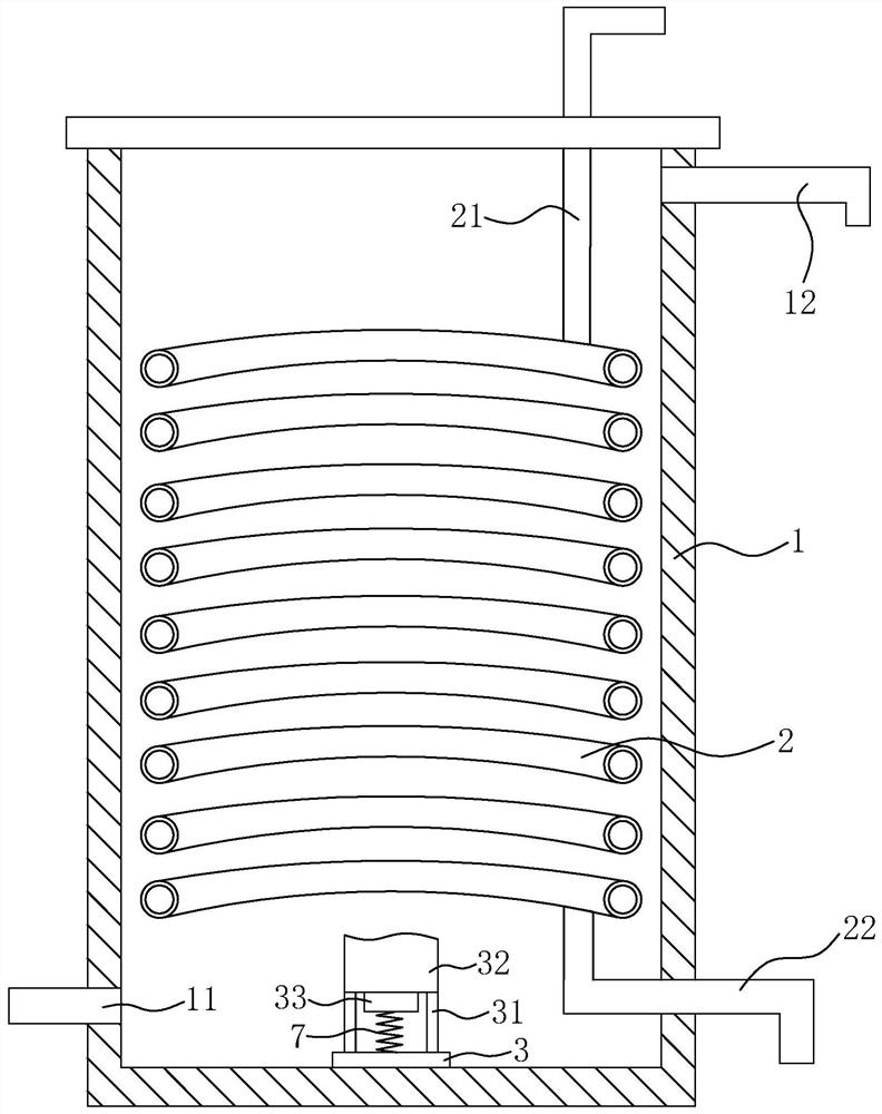
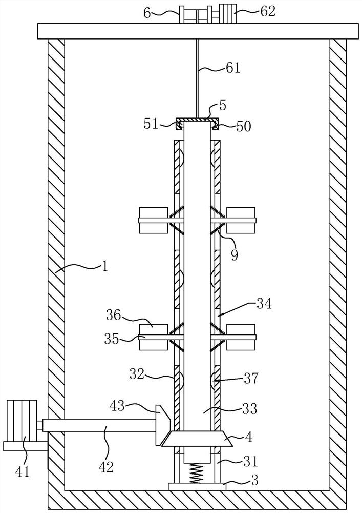
[0035] Embodiment 1: a kind of efficient cooling sampling device, such as figure 1 with figure 2 As shown, a water inlet 11 is provided at the bottom of the cooling barrel 1, and a water outlet 12 is provided at the top of the cooling barrel 1, so that the cooling barrel 1 can store cooling water; and a cooling pipeline is installed inside the cooling barrel 1 2. The cooling pipe 2 is spirally arranged vertically inside the cooling barrel 1, and the cooling pipe 2 is provided with a water inlet 21 and a sampling port 22. When sampling is required, the water inlet 21 of the cooling pipe 2 can be connected with the sample liquid , so that the sample liquid is cooled along the cooling pipe 2, and after the sample liquid is cooled by the cooling water in the cooling barrel 1, it can be discharged from the sampling port 22, and then the subsequent sample liquid detection is performed.

[0036] A turntable 3 is installed on the inner wall of the bottom of the cooling barrel body 1...

Embodiment 2

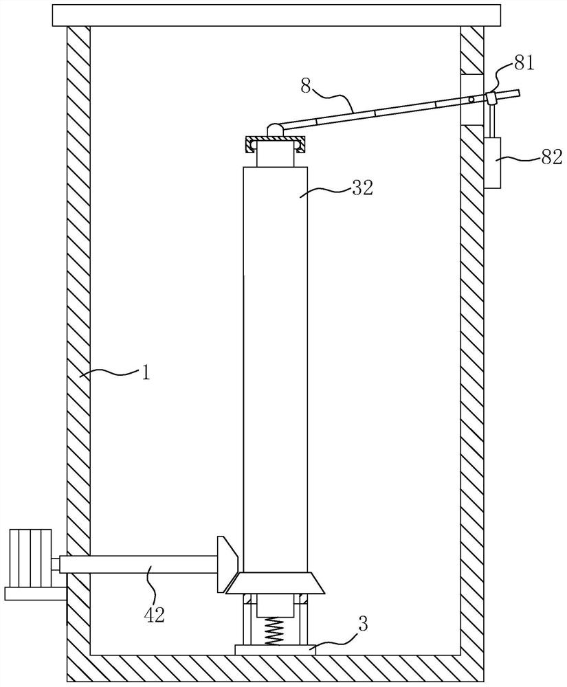
[0047] Embodiment 2: as image 3 As shown, the difference from Embodiment 1 lies in the difference of the lifter. In this embodiment, the lifter includes one end hinged on the top of the connecting block 5, and the other end horizontally passing through the telescopic rod 8 of the cooling barrel 1; The collar 81 on the telescoping rod 8 passes through the end; Then vertically be provided with the strip mouth that passes for telescopic rod 8, and telescopic rod 8 is hinged on the inwall of strip mouth.

[0048] When the cylinder 82 is opened, the piston rod of the cylinder 82 can drive the telescopic rod 8 to shake up and down, so that the telescopic rod 8 can rotate around the position of the strip opening, and the telescopic rod 8 can drive the connecting block 5 to lift up and down during the rotation process, thereby Drive the movable rod 33 to lift, and through this solution, the stirring blade 36 can also be driven to lift to realize the stirring of the cooling water.


PUM


Abstract

The invention relates to a high-efficiency cooling sampling device, which belongs to the technical field of cooling and liquefaction equipment. The main points of the technical solution are as follows: a cooling barrel body that holds cooling water and is provided with a water inlet and a water outlet; and a cooling barrel spirally arranged in the cooling barrel body. The cooling pipe is provided with a water inlet and a sampling port, and also includes: a turntable installed on the bottom wall of the cooling barrel; a drum; a stirring component installed on the empty drum; a driving component installed on the cooling barrel for driving the empty drum to rotate, so as to drive the stirring component to stir the cooling water in the cooling barrel; The lifting component for driving the stirring component to rise and fall. When the sampling device of the present invention is used, the cooling effect of the cooling water in the cooling barrel can be improved, so that the gas and liquid in the cooling pipe can be heated evenly, the failure of sampling can be reduced, and unnecessary troubles can be reduced.

Description

technical field [0001] The invention relates to the technical field of cooling liquefaction equipment, in particular to a high-efficiency cooling sampling device. Background technique [0002] The cooling sampling device is an instrument and equipment suitable for sampling and cooling steam and water in boiler rooms or power plants. It mainly includes a cooling barrel, a spring-shaped cooling pipe, and a flange cover, which can effectively improve the accuracy of water quality analysis. [0003] At present, the cooling barrel of the traditional cooling sampling device is generally set to store 20L of water. In this process, the valve of the cooling pipeline is generally opened first, so that the cooling liquid flows into the cooling pipeline, and then flows out from the cooling port of the barrel for cooling. The cooling water in the bucket will cool the liquid in the cooling pipe, so that the high-temperature liquid or gas can finally flow out as cooling water. [0004] Ho...

Claims


Application Information

Patent Timeline
Patent Type & Authority Patents(China)
IPC IPC(8): F28D7/02F28F13/12G01N1/10
CPCF28D7/02F28F13/125G01N1/10
Inventor 吴灵生
Owner 深圳市成大机电科技有限公司
Learn More