Electromagnetic valve and heat management method
A solenoid valve and thermal management technology, applied in the field of thermal management, can solve the problems of complex hardware structure of the solenoid valve control unit, and achieve the effect of low cost, high performance and restraining the temperature rise of the coil
- Summary
- Abstract
- Description
- Claims
- Application Information
AI Technical Summary
Problems solved by technology
Method used
Image
Examples
Embodiment 1
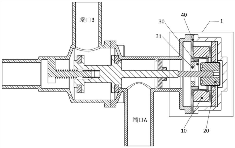
[0031] figure 1 A schematic structural diagram of a solenoid valve 1 according to an embodiment of the present disclosure is shown. and, figure 1 Also schematically shows the structure of the pipeline provided with the solenoid valve 1 . Such as figure 1 As shown, similar to the existing solenoid valve, the solenoid valve 1 of the embodiment of the present disclosure includes: a coil 10 and a magnetic core 20 . In this case, an electromagnetic field is formed when the coil 10 is energized and disappears after the coil 10 is de-energized. The magnetic core 20 operates according to the electromagnetic force generated by the electromagnetic field formed by energizing the coil 10 to control the fluid flowing in the pipeline where the electromagnetic valve 1 is installed. Specifically, under the action of electromagnetic force, the magnetic core 20 can change the opening degree of the port A and the opening degree of the port B, so as to distribute the flow of the fluid flowing...
Embodiment 2
[0049] As mentioned in the disadvantage (3) of the existing solenoid valve in the background technology section, as the coil temperature increases, the temperature resistance of the coil will decrease, which will finally affect the control performance of the solenoid valve, such as linear control performance, etc. . In other words, the coil temperature plays a crucial role in ensuring the temperature resistance of the coil and the control performance of the solenoid valve. Therefore, in order to perform linear control of the solenoid valve, it is necessary to accurately sense the temperature of the coil.
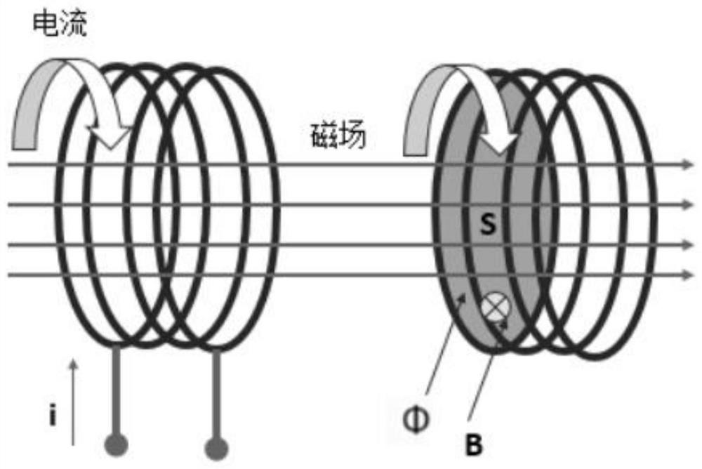
[0050] However, as described in the disadvantage (4) of the existing solenoid valve in the background technology section, in order to control the temperature resistance of the coil of the solenoid valve, a temperature sensor needs to be additionally provided, and this will lead to changes in the hardware structure of the solenoid valve control unit. more complicated. In or...
Embodiment 3
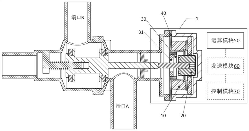
[0075] On the basis of the above-mentioned embodiment 2 of the present disclosure, as image 3 As shown, the solenoid valve according to the embodiment of the present disclosure further includes a sending module 60 . Wherein, the sending module 60 is connected with the computing module 50, and is used to transmit the temperature T of the coil 10 calculated by the computing module 50 at the K+1th moment k+1 sent to the thermal management system, wherein the thermal management system is based on the temperature T of the coil 10 at the K+1th moment k+1 To control the current applied to the coil 10 for corresponding thermal management.
[0076] Among them, the sending module of the embodiment of the present disclosure can be, for example, a communication module that can communicate with the thermal management system through short-distance communication such as Bluetooth or NFC, or can communicate with the thermal management system through long-distance communication such as a wir...
PUM
 Abstract
Description
Claims
Application Information
 - R&D Engineer
- R&D Manager
- IP Professional
- Industry Leading Data Capabilities
- Powerful AI technology
- Patent DNA Extraction
Browse by: Latest US Patents, China's latest patents, Technical Efficacy Thesaurus, Application Domain, Technology Topic, Popular Technical Reports.
© 2024 PatSnap. All rights reserved.Legal|Privacy policy|Modern Slavery Act Transparency Statement|Sitemap|About US| Contact US: help@patsnap.com


