Hydraulic oil tank

A technology of hydraulic oil tank and oil chamber, applied in the field of hydraulic system, can solve the problems of poor performance, inability to greatly reduce the hydraulic oil temperature of the oil chamber, and the increase of the hydraulic oil temperature.

Pending Publication Date: 2020-10-27
重庆龙归换热器科技有限公司
View PDF2 Cites 0 Cited by
  • Summary
  • Abstract
  • Description
  • Claims
  • Application Information

AI Technical Summary

Problems solved by technology

[0004] As mentioned above, when the hydraulic oil tank is used in the hydraulic system, there are some disadvantages in the use process: first, due to the poor performance of the domestic ordinary pump, it is easy to cause the hydraulic oil temperature to rise quickly and relatively large; The heat exchange tube of the fuel tank has average heat dissipation performance and cannot greatly reduce the hydraulic oil temperature
Even if the Nissan (produced in Japan) pump with excellent performance is used, it can only overcome the problem of rapid and large hydraulic oil temperature rise to a certain extent, and cannot greatly reduce the hydraulic oil temperature in the oil chamber, and the use of Nissan pumps will greatly reduce the temperature of the hydraulic oil. Increase the production cost of hydraulic oil tanks. Taking the production of a hydraulic oil tank as an example, the cost of domestic ordinary pumps is about 1,000-1,500 yuan / set, while the cost of Nissan pumps is as high as 4,000-8,000 yuan / set
In addition, the oil storage capacity of the existing hydraulic oil tank is completely determined by the size of the oil chamber. To increase the oil storage capacity, the volume of the oil chamber and the hydraulic oil tank must be increased, which not only wastes the installation space of the hydraulic oil tank, but also further increases the capacity of the hydraulic oil tank. In addition, the cooling effect of the existing ordinary hydraulic oil tank is not ideal, even if the existing Nissan high-performance hydraulic oil tank is used, usually the temperature of the cooled hydraulic oil can only be controlled at a temperature of 52-55 °C

Method used


Image

  • Hydraulic oil tank
  • Hydraulic oil tank
  • Hydraulic oil tank

Examples


Embodiment 1

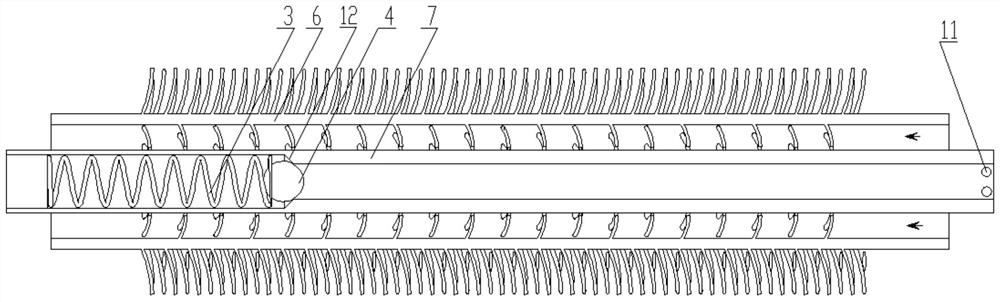
[0024] A hydraulic tank, such as figure 1 and figure 2 As shown, it includes a low-temperature oil chamber 2 and a high-temperature oil chamber 10. The oil supply port of the low-temperature oil chamber 2 is connected to the oil supply pipeline 1 and the pump 5. An on-off valve is arranged on the oil supply pipeline 1. The oil return of the high-temperature oil chamber 10 The port is connected to the oil return pipeline 1, and the low-temperature oil chamber 2 is connected to the high-temperature oil chamber 10 through a heat exchange tube. A fan is installed on the side of the heat exchange tube, and the wind introduced by the fan is used as the cooling medium of the heat exchange tube; The pipe is used to connect the low-temperature oil chamber 2 and the high-temperature oil chamber 10. An inner pipe is arranged axially in the casing. Within the allowable pressure, the inner pipe is a non-conductive structure, and the gap between the outer wall of the inner pipe and the inn...

Embodiment 2

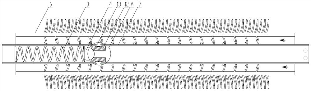
[0034] A hydraulic tank, such as figure 1 , image 3 and Figure 4 As shown, it includes a low-temperature oil chamber 2 and a high-temperature oil chamber 10. The oil supply port of the low-temperature oil chamber 2 is connected to the oil supply pipeline 1 and the pump 5. An on-off valve is arranged on the oil supply pipeline 1. The oil return of the high-temperature oil chamber 10 The port is connected to the oil return pipeline 1, and the low-temperature oil chamber 2 is connected to the high-temperature oil chamber 10 through a heat exchange tube. A fan is installed on the side of the heat exchange tube, and the wind introduced by the fan is used as the cooling medium of the heat exchange tube; The pipe is used to connect the low-temperature oil chamber 2 and the high-temperature oil chamber 10. An inner pipe is arranged axially in the casing. Within the allowable pressure, the inner pipe is a non-conductive structure, and the gap between the outer wall of the inner pipe...

Embodiment 3

[0044] A hydraulic oil tank. Referring to Embodiment 1, the difference between it and Embodiment 1 is that the gap between the outer wall of the inner tube A of the first heat exchange tube and the inner ring of the casing A is 1 mm.


PUM


Abstract

The invention provides a hydraulic oil tank. The hydraulic oil tank comprises a low-temperature oil chamber and a high-temperature oil chamber, wherein an oil supply port of the low-temperature oil chamber is connected with an oil supply pipeline and a pump, an oil return port of the high-temperature oil chamber is connected with an oil return pipeline, the low-temperature oil chamber is connectedwith the high-temperature oil chamber through a heat exchange tube, a fan is arranged at the side of the heat exchange tube, and air introduced by the fan serves as a heat exchange tube cooling medium; and the heat exchange tube comprises a sleeve for communicating with the low-temperature oil chamber and the high-temperature oil chamber, an inner tube is axially arranged in the sleeve, the innertube is a non-conducting structure in the allowable pressure, and the gap between the outer wall of the inner tube and an inner ring of the sleeve is controlled to be 1-10 mm. The hydraulic oil tankis simple in structure, easy to clean, easy to manufacture and high in cost performance.

Description

technical field [0001] The invention relates to a hydraulic system, in particular to a hydraulic oil tank. Background technique [0002] Hydraulic oil tanks are widely used in hydraulic systems such as automobiles, construction machinery, and petrochemical equipment. The heat generated by the hydraulic system is dissipated, and the high-temperature hydraulic oil after a working cycle can be returned to the hydraulic oil tank for cooling, so that the oil temperature can be controlled within the required range; the hydraulic oil will be cleaned after a working cycle Dirt is generated, which can settle through the hydraulic tank. [0003] There are many types of hydraulic oil tanks. For example, commonly used hydraulic oil tanks include high-temperature oil chambers and low-temperature oil chambers. On the one hand, the high-temperature oil chambers and low-temperature oil chambers are connected through heat exchange tubes, and on the other hand, they are connected through oil...

Claims


Application Information

Patent Timeline
Patent Type & Authority Applications(China)
IPC IPC(8): F15B1/26F15B21/0423
CPCF15B1/26F15B21/042
Inventor 彭程林崔志明
Owner 重庆龙归换热器科技有限公司
Why Eureka
Try Eureka