Steel structure and mounting method thereof

An installation method and technology of steel structure, applied in the direction of structural elements, building components, building structure, etc., can solve the problems of deformation of the top beam and bottom beam of the steel structure, affecting the construction effect of the building structure strength, etc., so as to avoid deformation problems and ensure Relative stability, sliding stability effect

Inactive Publication Date: 2020-10-27
CHINA CONSTR STEEL STRUCTURE CORP LTD
View PDF7 Cites 0 Cited by
  • Summary
  • Abstract
  • Description
  • Claims
  • Application Information

AI Technical Summary

Problems solved by technology

[0003] Therefore, the technical problem to be solved by the present invention is to overcome the defect that the existing steel structure top beam and bottom beam are easily deformed, which affects the construction effect and the structural strength of the building.

Method used


Image

  • Steel structure and mounting method thereof
  • Steel structure and mounting method thereof
  • Steel structure and mounting method thereof

Examples


specific Embodiment approach

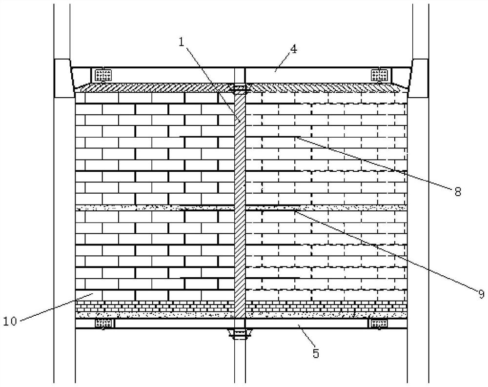
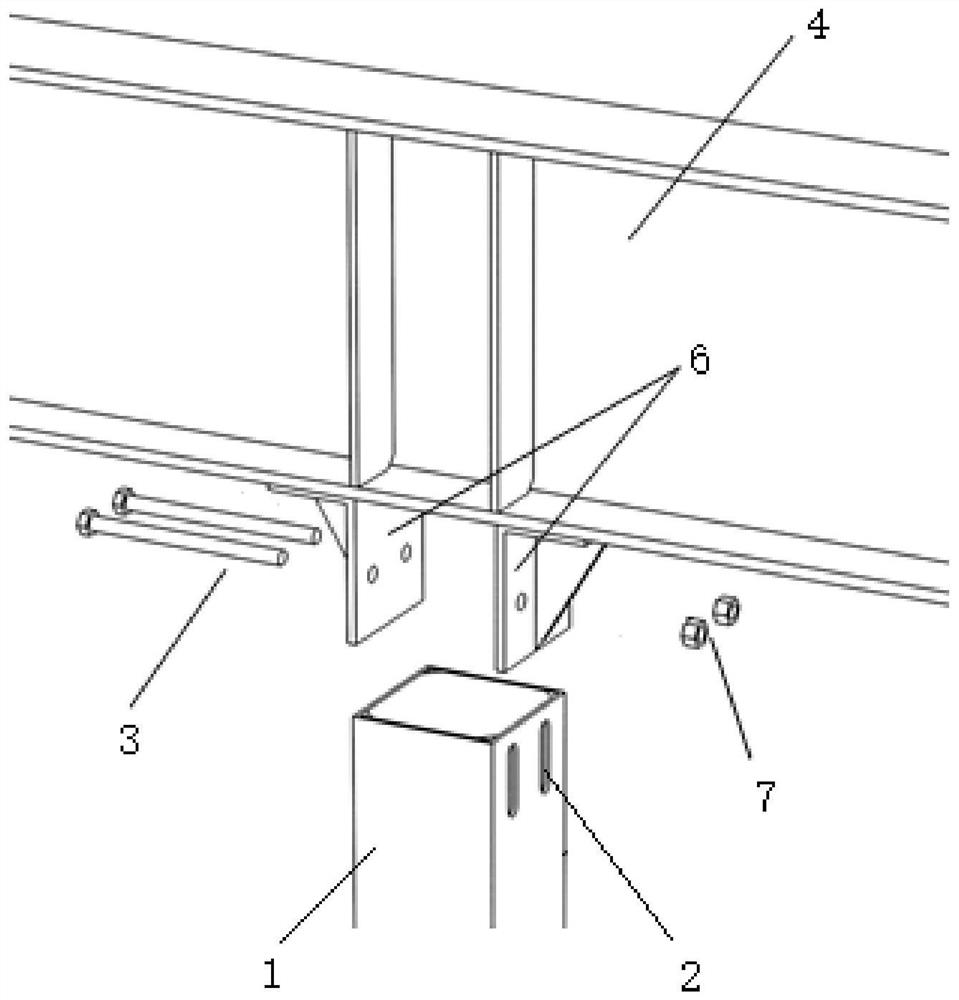
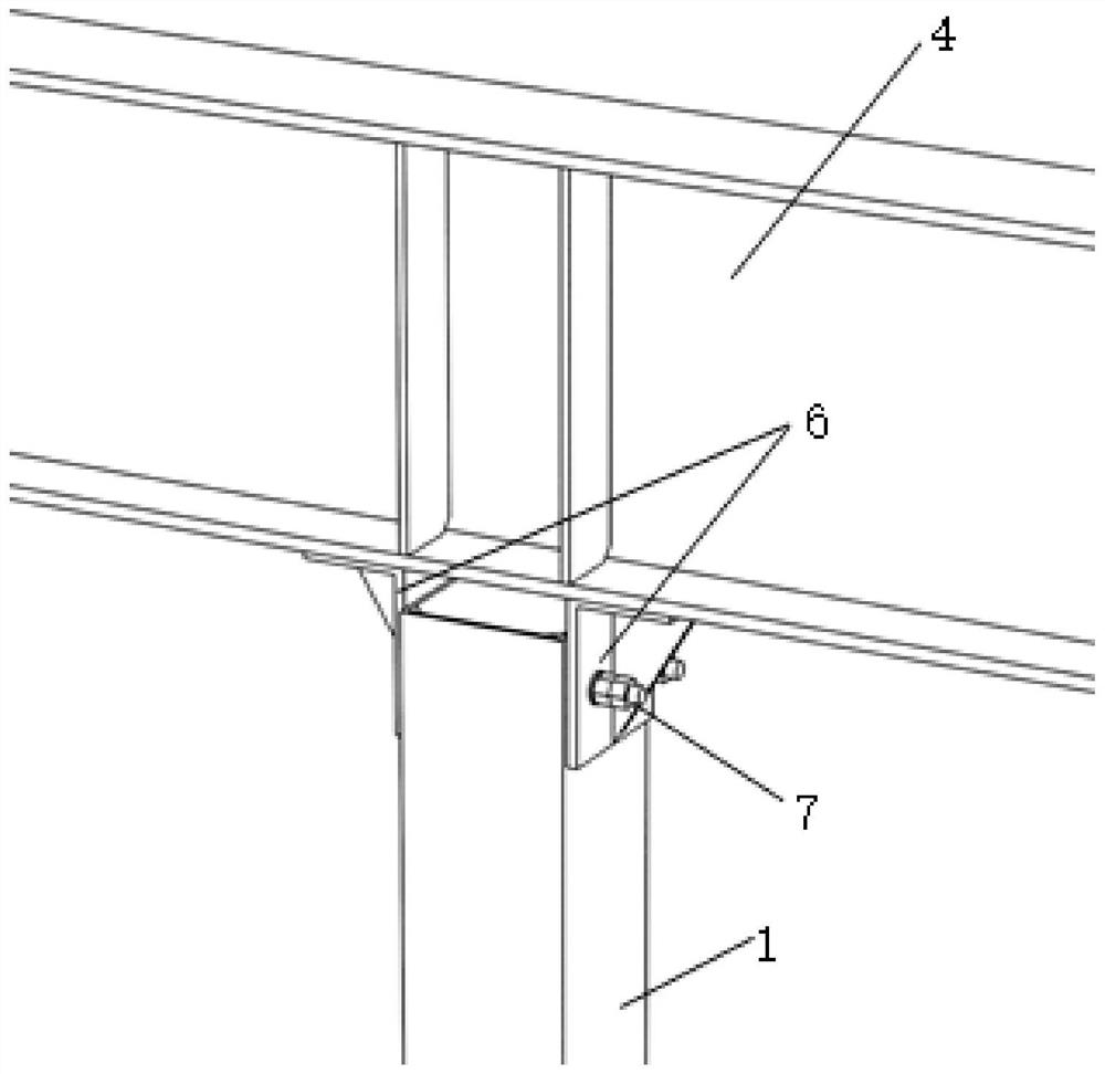
[0042] Such as Figures 1 to 5 A specific implementation of the installation method of the steel structure shown includes the following steps: fixing the lower end of the column 1 and the middle part of the bottom beam 5 by welding, placing the top beam 4 on the upper end of the column 1, and using the slider 3 to pass through the Set in the connecting piece 6 and the slideway 2, the sliding piece 3 is a bolt, and the sliding piece 3 and the connecting piece 6 are fixed on the upper end of the slideway 2 through the nut as the fastener 7, the connecting piece 6 is an angle steel, and the column 1 A sliding space for the top beam 4 is formed between the top of the top and the two connectors 6. When the floor is installed on the top beam 4, under the gravity of the floor, the top beam 4 slides in the sliding space, that is, sliding Part 3 slides from the upper end of slideway 2 to the lower end of slideway 2 .

[0043] When the steel structure provided by this embodiment is in ...


PUM


Abstract

The invention relates to the technical field of building structures, in particular to a steel structure and a mounting method thereof. The steel structure provided by the invention comprises a top beam and a bottom beam which are oppositely arranged, and a stand column, wherein the two ends of the stand column are separately connected to the top beam and the bottom beam; the top beam faces towardsa slide space for allowing the stand column to move under action of external force reserved on one end, connected to the top beam, of the stand column. According to the steel structure provided by the invention, while floor is mounted on the top beam, the top beam downwards slides under action of gravity of the floor, so that gravity of the floor is directly acted on the stand column, and therefore, certain buffer effect is achieved, the deformation problem due to the fact that the top beam and the bottom beam are directly stressed is avoided, and construction effect and structural strength of a building are guaranteed.

Description

technical field [0001] The invention relates to the technical field of building structures, in particular to a steel structure and an installation method thereof. Background technique [0002] Steel structures are widely used in new buildings because of their convenience in construction. Compared with traditional concrete buildings, steel structures have higher strength and better earthquake resistance. Since most of the steel components are pre-processed in the factory and then installed on site, the on-site construction pollution is small, the degree of mechanization is high, the labor cost is reduced, and the efficiency is improved. Therefore, more and more engineering projects use steel structures. However, in the prior art, the top beam and the bottom beam are directly placed on the corresponding positions of the steel structure columns, and are fixedly connected by fasteners, so that when the floor is installed on the top beam, it is easy to produce a Deformation, so...

Claims


Application Information

Patent Timeline
IPC IPC(8): E04B1/24E04B1/58E04B2/02E04C5/01
CPCE04B1/24E04B1/2403E04B1/58E04B2/02E04C5/01E04B2001/2406
Inventor 王康龙方春生陈韬张瑜禚春维徐业明徐书华王春林李鹏飞
Owner CHINA CONSTR STEEL STRUCTURE CORP LTD
Why Eureka
Try Eureka