
Automatic deviation correcting device for upper belt surface and lower belt surface of conveyor

A technology of automatic deviation correction device and conveyor, applied in the direction of conveyor control device, conveyor, conveyor objects, etc., can solve the problems of scattering, tearing tape, deviation and so on

Pending Publication Date: 2020-10-27
北京冠明机械科技有限公司
View PDF0 Cites 1 Cited by
  • Summary
  • Abstract
  • Description
  • Claims
  • Application Information

AI Technical Summary

Problems solved by technology

[0002] During the operation of the belt conveyor, deviation will occur due to many external factors, and deviation will cause problems such as material spreading and belt tearing
In view of the above-mentioned belt deviation situation, at present, the belt deviation is mainly controlled by adjusting the angle of the idler roller or increasing the height of the idler roller. These two methods are often realized manually or after the shutdown, which forces the belt post worker to The increase in labor intensity has also brought great potential safety hazards to personnel safety. At the same time, the continuity of production has been interrupted, which has affected the benefits of enterprises.

Method used


Image

  • Automatic deviation correcting device for upper belt surface and lower belt surface of conveyor
  • Automatic deviation correcting device for upper belt surface and lower belt surface of conveyor
  • Automatic deviation correcting device for upper belt surface and lower belt surface of conveyor

Examples


Embodiment Construction

[0022] The following examples are used to illustrate the present invention, but are not intended to limit the scope of the present invention.

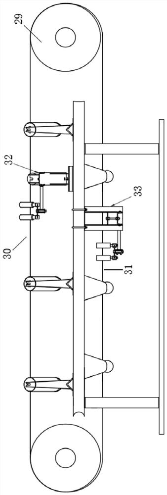
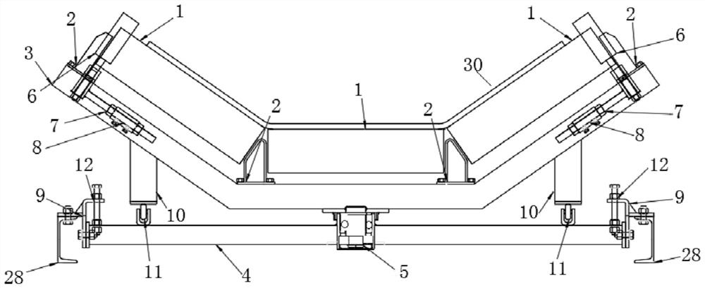
[0023] An automatic deviation correcting device for the upper belt surface and the lower belt surface of the conveyor of the present invention, the automatic deviation correction device for the upper belt surface of the conveyor is provided on the upper belt surface of the conveyor, and the lower belt surface of the conveyor is provided on the lower belt surface of the conveyor. The automatic deviation correction device for the belt surface on the conveyor includes three idler rollers, idler support seats, rotating upper beams, lower beams, rotating shafts, double detection rollers, double detection roller adjustment screw rods, and connecting rods. , a mounting plate, a support plate, a support wheel, and an adjusting screw, the three idlers are located below the upper belt surface, and the three idlers are installed on the roller supp...


PUM


Abstract

The invention relates to an automatic deviation correcting device for an upper belt surface and a lower belt surface of a conveyor. The automatic deviation correcting device is characterized in that three carrier rollers are positioned below the upper belt surface and are sequentially installed on carrier roller supporting seats, the carrier roller supporting seats are bolted on an upper rotatingcross beam, and the upper rotating cross beam and a rotating shaft are welded into a whole to be inserted into a lower cross beam bearing group to be fastened; double detection rollers and double detection roller adjusting lead screws are welded into a whole to be inserted into sleeves on connecting rods, the two ends of each sleeve are locked through nuts, the connecting rods are bolted on the two ends of the upper rotating beam, the supporting plates are welded to the two sides of the lower part of the upper rotating beam, and supporting wheels are installed on U-shaped bases which are welded to a lower cross beam; and mounting plates are bolted on the two ends of the lower cross beam, adjusting screws are bolted above the two ends of the lower cross beam, the top ends of the adjusting screws are fastened with mounting plate nuts, and the tail ends of the adjusting screws are fastened with lower cross beam nuts. The automatic deviation correcting device does not need a power supply and shutdown operation, is low in price, high in reliability and free of maintenance, and can realize deviation correction of the upper belt surface and the lower belt surface of the belt conveyor.

Description

technical field [0001] The invention relates to equipment for transfer belts, in particular to an automatic deviation correction device for the upper belt surface and the lower belt surface of a conveyor. Background technique [0002] During the operation of the belt conveyor, deviation will occur due to many external factors, and deviation will cause problems such as material spreading and belt tearing. In view of the above-mentioned belt deviation situation, at present, the belt deviation is mainly controlled by adjusting the angle of the idler roller or raising the idler roller, and these two methods are often realized manually or after the shutdown, which forces the belt post worker to The increase in labor intensity has also brought great potential safety hazards to personnel safety. At the same time, the continuity of production has been interrupted, which has affected the benefits of enterprises. Contents of the invention [0003] The object of the present inventio...

Claims


Application Information

Patent Timeline
Patent Type & Authority Applications(China)
IPC IPC(8): B65G15/64B65G39/16B65G43/00
CPCB65G15/64B65G39/16B65G43/00
Inventor 李明
Owner 北京冠明机械科技有限公司
Learn More