
Novel precast beam bottom form and construction method thereof

A technology of prefabricated beams and bottom molds, applied in manufacturing tools, ceramic molding machines, mold separation devices, etc., can solve the problems of occupying land, no bottom molds, and reducing the production efficiency of prefabricated beams.

Inactive Publication Date: 2020-10-27
GUANGDONG PROVINCIAL ARCHITECTURAL ENG MACHINERY CONSTR
View PDF10 Cites 0 Cited by
  • Summary
  • Abstract
  • Description
  • Claims
  • Application Information

AI Technical Summary

Problems solved by technology

[0004] 1. For prefabricated beams with less used specifications and fewer production quantities, there are usually bottom forms without corresponding specifications. It is necessary to remove the original bottom form and remake the corresponding specification bottom form to meet the production. This repeated operation greatly reduces the cost of prefabricated beams. production efficiency, but also a waste of materials and labor
[0005] 2. When the prefabricated beam factory needs to produce prefabricated beams of various specifications, it needs to prepare bottom forms of various specifications, which requires a lot of manpower and material resources to install the bottom form, and also occupies too much land, resulting in waste and vacancy
[0006] 3. There are many specifications of prefabricated beams. If it is necessary to meet the production of prefabricated beams of various specifications, it is necessary to make bottom molds of various specifications for production, and manual maintenance is also required.

Method used


Image

  • Novel precast beam bottom form and construction method thereof
  • Novel precast beam bottom form and construction method thereof
  • Novel precast beam bottom form and construction method thereof

Examples


Embodiment Construction

[0032] The preferred embodiments of the present invention will be described in detail below in conjunction with the accompanying drawings, so that the advantages and features of the present invention can be more easily understood by those skilled in the art, so as to define the protection scope of the present invention more clearly.

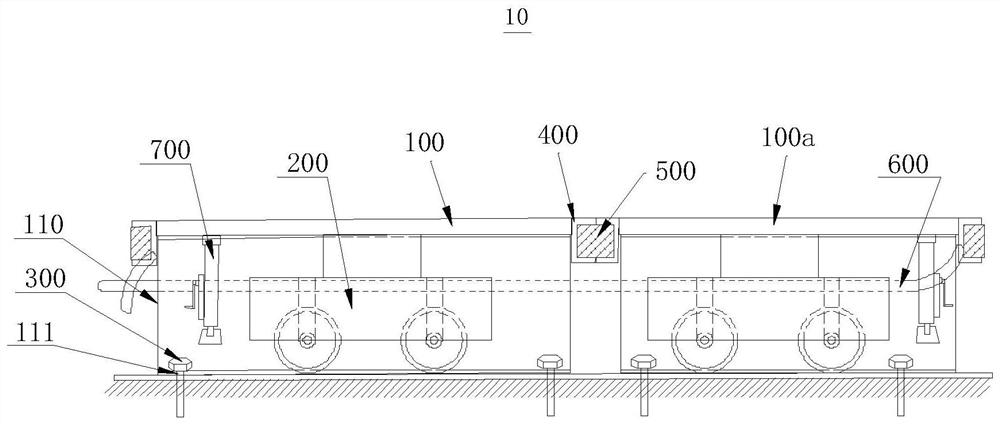
[0033] see figure 1 , which is a structural schematic diagram of a new type of precast beam bottom form 10 according to an embodiment of the present invention. A new type of prefabricated beam bottom form 10 includes a steel plate bottom form 100, a moving system 200 and a positioning member 300, the moving system 200 is arranged on the steel plate bottom form 100, and the moving system 200 is used to drive the steel plate bottom form 100 to move the steel plate bottom form to a preset area, that is, the movement of the moving system 200 drives the steel plate bottom form 100 to move, so as to facilitate the subsequent splicing operation of the s...


PUM


Abstract

The invention relates to a novel precast beam bottom form. The bottom form comprises steel sheet bottom forms, a moving system and a positioning piece, wherein the positioning piece is used for fixingthe steel sheet bottom forms, the moving system is arranged on the steel sheet bottom forms, so that flexible moving and splicing combining of the steel sheet bottom forms can be achieved, the construction efficiency is improved, and the mechanical machine-team and labor for changing precast specifications are saved. According to the bottom form, due to the fact that spliced bottom forms and themoving system are fixed into a movable system, moving and splicing can be conducted on the steel sheet bottom forms in the horizontal direction, the steel bar, steel sheet bottom form and concrete construction can be subjected to continuous integrated operation, and the deviation of the steel sheet bottom forms is not affected; and then, the steel sheet bottom forms are simple in structure, materials are easy to obtain, rapid splicing can be achieved through the moving system, channel steel is welded to connectors on the two sides of the spliced steel sheet bottom forms, and any two adjacent steel sheet bottom forms can be spliced into the spliced bottom forms of different specifications.

Description

technical field [0001] The invention relates to the technical field of prefabricated beam bottom formwork, in particular to a novel prefabricated beam bottom formwork and a construction method thereof. Background technique [0002] As we all know, prefabricated beams are prefabricated in factories, and then transported to the construction site to be installed and fixed according to the design requirements. [0003] However, existing problems still exist when making prefabricated beams: [0004] 1. For prefabricated beams with less used specifications and fewer production quantities, there are usually bottom forms without corresponding specifications. It is necessary to remove the original bottom form and remake the corresponding specification bottom form to meet the production. This repeated operation greatly reduces the cost of prefabricated beams. High production efficiency, but also a waste of materials and labor. [0005] 2. When the prefabricated beam factory needs to...

Claims


Application Information

Patent Timeline
IPC IPC(8): B28B7/00B28B7/26
CPCB28B7/0011B28B7/0014B28B7/26
Inventor 陈健平潘伟根李伟才
Owner GUANGDONG PROVINCIAL ARCHITECTURAL ENG MACHINERY CONSTR
Learn More