Glove assembly for glove box and glove fixing ring
A technology of glove box and fixing ring, which is applied in the field of glove box and can solve problems such as easy damage
- Summary
- Abstract
- Description
- Claims
- Application Information
AI Technical Summary
Problems solved by technology
Method used
Image

Examples
Embodiment 1
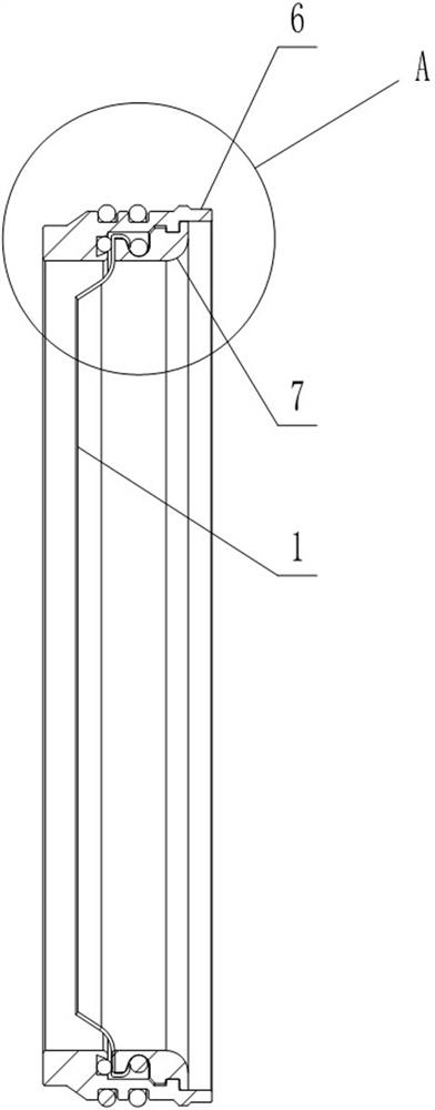
[0029] like figure 1 and figure 2 As shown, the glove assembly for the glove box includes a glove 1 and a fixing ring arranged at the mouth of the glove 1, and the lead-out position of the glove 1 on the fixing ring is located on the inner wall of the fixing ring.
[0030] In the prior art, for the application that the glove 1 needs to be pushed to the inside of the glove box, and then taken out from the inside of the glove box through the waste outlet, during the replacement process of the glove 1, the entire glove assembly including the glove 1 and the fixing ring is generally replaced. The specific operation method is generally: use a special pushing tool to push the replacement glove assembly (including the glove assembly of the new glove) inward from the outside of the glove 1 installation port on the glove box. When the inner end of the fixing ring is squeezed with the outer end of the fixing ring on the replaced glove assembly (including the glove assembly of the old ...
Embodiment 2
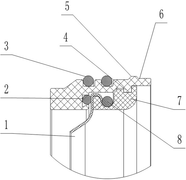
[0035] like figure 1 and figure 2 As shown, this embodiment is further limited on the basis of Embodiment 1: as a technical solution that facilitates the sealing effect between the glove 1 and the fixing ring, it is set as follows: the fixing ring includes a first set of tube-shaped Ring 7 and the second collar 6; the center hole of the second collar 6 is in the shape of a stepped shaft; the first collar 7 is embedded in the center hole of the second collar 6 by one end of the second collar 6, And the position of the first collar 7 on the axis of the second collar 6 is constrained on the shoulder of the central hole; the glove 1 is partially clamped on the shoulder and the first collar 7 goes deep into the central hole On the mating surface between the end surfaces of the glove 1, the glove 1 extends from the position of the shoulder to the inside of the inner wall. This solution adopts the method of local pressure on the opening of the glove 1 to complete the connection be...
Embodiment 3
[0037] like figure 1 and figure 2 As shown, this embodiment is further limited on the basis of embodiment 2: as a realization scheme of a fixed ring with a simple structure and easy assembly, it is set as follows: the first collar 7 and the second collar 6 are clamped and connected : Of the hole wall of the central hole and the side wall of the first collar 7, one of them is provided with a first buckle protrusion 4, and the other is provided with a Matching first buckle groove, the position of the first collar 7 on the axis of the second collar 6 is fixed by the following method: the end of the first collar 7 that goes deep into the center hole is constrained on the shoulder of the center hole, so The first buckle protrusion 4 is embedded in the first buckle groove. In this solution, when the first collar 7 is inserted into the second collar 6, the shaft shoulder is locked at the dead point in the direction of motion, and at the same time, the mating surface can be used to...
PUM
 Abstract
Description
Claims
Application Information
 - Generate Ideas
- Intellectual Property
- Life Sciences
- Materials
- Tech Scout
- Unparalleled Data Quality
- Higher Quality Content
- 60% Fewer Hallucinations
Browse by: Latest US Patents, China's latest patents, Technical Efficacy Thesaurus, Application Domain, Technology Topic, Popular Technical Reports.
© 2025 PatSnap. All rights reserved.Legal|Privacy policy|Modern Slavery Act Transparency Statement|Sitemap|About US| Contact US: help@patsnap.com