
An automatic pressing machine

A technology of automatic pin pressing and final pressing, applied in metal processing equipment, metal processing, manufacturing tools, etc., can solve the problems of prone to errors, inaccurate elastic cotter pin direction, low efficiency, etc., to achieve the effect of convenience, intelligence and intelligence

Active Publication Date: 2021-10-08
深圳市优迪泰自动化科技有限公司
View PDF7 Cites 0 Cited by
  • Summary
  • Abstract
  • Description
  • Claims
  • Application Information

AI Technical Summary

Problems solved by technology

[0004] The purpose of the present invention is to provide an automatic depressing machine to solve the problem that the depressing machine proposed in the above background technology has a large connection error in the process of transferring the rotating shaft and is prone to mistakes. At the same time, most of the depressing machines are currently Both still use the method of manual feeding, which leads to inaccurate identification of the direction of the elastic cotter pin, low efficiency, and high misjudgment rate.

Method used


Image

  • An automatic pressing machine
  • An automatic pressing machine
  • An automatic pressing machine

Examples


Embodiment Construction

[0024] The following will clearly and completely describe the technical solutions in the embodiments of the present invention with reference to the accompanying drawings in the embodiments of the present invention. Obviously, the described embodiments are only some, not all, embodiments of the present invention. Based on the embodiments of the present invention, all other embodiments obtained by persons of ordinary skill in the art without making creative efforts belong to the protection scope of the present invention.

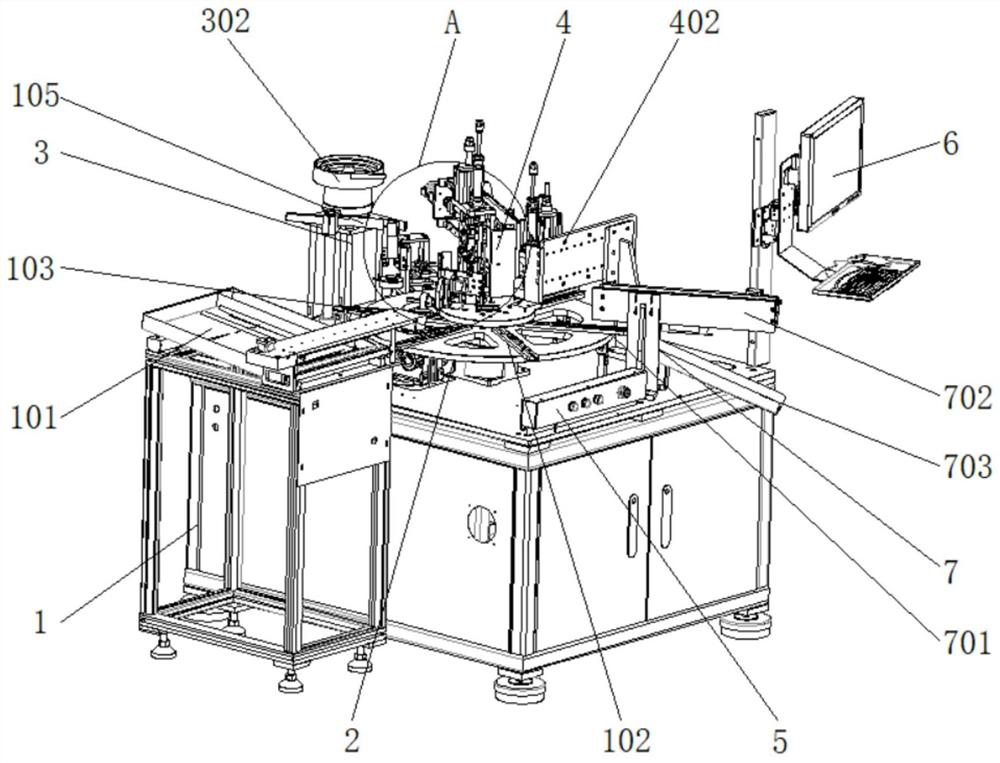
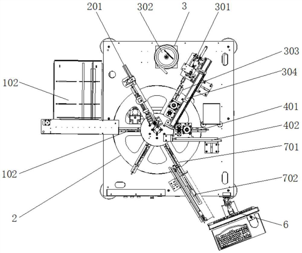
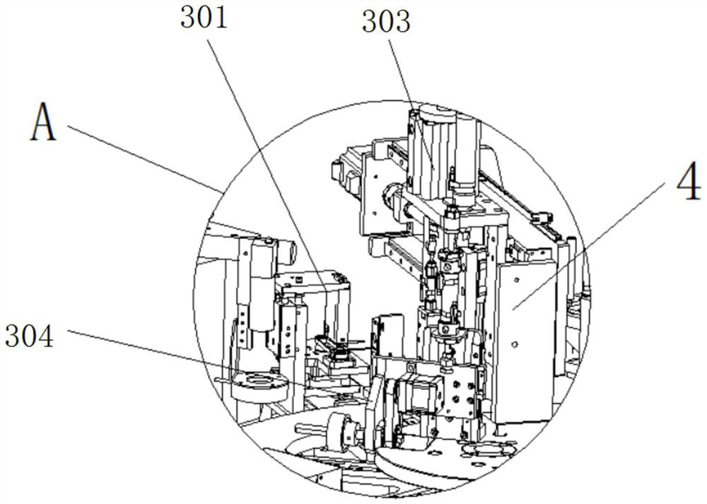
[0025] see Figure 1-3, the present invention provides a technical solution: an automatic pin pressing machine, including a main body 1, a rotating shaft feeding assembly 101, a rotating shaft feeding station 102, a rotating shaft hole alignment station 103, a rotating shaft hole rotating assembly, and a rotating shaft hole direction detection Component 105, jig 2, feeding mechanism 3, elastic cotter pin feeding component 301, elastic cotter pin vibrating plat...


PUM


Abstract

The invention discloses an automatic pin pressing machine, which includes a main body, a feeding mechanism and a power button box. A rotating shaft feeding assembly is installed above the main body. A jig is arranged at the bottom end of the rotating shaft feeding assembly. The feeding mechanism is installed on the outside of one end of the main body, and a processing mechanism is installed above the main body. The power button box is installed on the upper side of the main body close to the right side. mechanism, and an unloading mechanism is installed above the end of the jig close to the power button box. The automatic pin pressing machine is equipped with a feeding mechanism, the collet on the elastic cotter pin pre-pressing assembly moves to the top of the dock elastic cotter pin, clamps the elastic cotter pin and moves to the hole position of the rotating shaft, and first fixes the rotating shaft in the jig , and then the elastic cotter pin preloading assembly puts it into the shaft hole, thereby solving the phenomenon that the direction of the elastic cotter pin is inaccurate, its efficiency is low, and the misjudgment rate is large.

Description

technical field [0001] The invention relates to the technical field of depressing machines, in particular to an automatic depressing machine. Background technique [0002] At present, in the field of auto parts stamping, auto parts need to be assembled with U-shaped forks, and spring pins are required for its fixation. Traditional spring pins need to be placed and pressed in manually, and they are easy to be tilted during operation, resulting in that the spring pins cannot be accurately pressed into the auto parts. In the assembled U-shaped fork, the defect rate is high and the production efficiency is low. This equipment involves the field of automatic press-fitting of pins, and involves the opening direction of the optical fiber grabbing elastic pin, the direction of the visual alignment shaft hole, and the opening to be aligned. The elastic pin is pressed into the hole of the rotating shaft and the depth dimension of its pressing is guaranteed to be within the tolerance r...

Claims


Application Information

Patent Timeline
Patent Type & Authority Patents(China)
IPC IPC(8): B23P19/02B23P19/00
CPCB23P19/001B23P19/002B23P19/007B23P19/02
Inventor 张晶邓正全闵子璞邹圣喜梁子坚
Owner 深圳市优迪泰自动化科技有限公司
Learn More