
A circuit and method for improving power grid power quality

A power quality and circuit technology, applied in the field of circuits to improve the power quality of the power grid, can solve the problems of increased volume, increased cost, and decreased conversion efficiency, and achieves the effects of increasing inductance, reducing cost, and improving conversion efficiency.

Active Publication Date: 2020-12-22
GOLDEN SCORPION CO LTD
View PDF6 Cites 0 Cited by
  • Summary
  • Abstract
  • Description
  • Claims
  • Application Information

AI Technical Summary

Problems solved by technology

A general switching power supply circuit includes an inductor. The coil and iron core have losses during the power conversion process, which reduces the conversion efficiency. Increase the number of coil turns or use a more expensive core to reduce energy loss and increase the conversion rate, but lead to volume changes. big, cost increase

Method used


Image

  • A circuit and method for improving power grid power quality
  • A circuit and method for improving power grid power quality
  • A circuit and method for improving power grid power quality

Examples


Embodiment

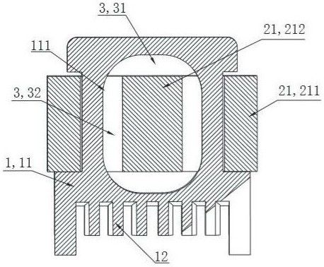
[0046] See attached Figure 8 The circuit for improving the power quality of the power grid of the present invention includes a rectifying and filtering circuit connected to the input terminal of the grid, a power factor correction circuit, a high-frequency inverter circuit, a control circuit and an output terminal, and the high-frequency inverter circuit includes a magnetic Coupled magnetic core and coil, the coil is wound on the insulating structure, and a part of the magnetic core is arranged in the hollow channel of the insulating structure.

[0047] In one embodiment of the present invention, the magnetic coupling between the magnetic core and the coil is an inductance, and the circuit for improving the power quality of the grid is a switching power supply circuit of a power conversion device.

[0048] Such as Figure 5 as shown, Figure 5 For the magnetic core structure of the embodiment of the present invention, in Figure 5 The distribution of the main magnetic flux...

Embodiment 4

[0080] This embodiment is basically the same as Embodiment 1, the difference is:

[0081] see image 3 , the number of air gaps is five, and the width of each air gap is δ1, δ2, δ3, δ4, δ5, and satisfies δ1+δ2+δ3+δ4+δ5=8mm.

[0082] In this embodiment, δ1=δ2=δ3=δ4=1mm, δ5=4mm.

[0083] It should be noted that, among the five air gaps, there are two air gaps on each magnetic core 2, that is, the part of the magnetic core 2 extending into the core slot 11 is divided into three sections, and each section is connected in turn by an insulating pad, and each section The magnetic cores 2 are separated from each other to form an air gap.

[0084] In actual production, a single magnetic core 2 is segmented, and then the segmented magnetic core 2 is tightly pressed together with an insulating pad to form a magnetic core with an air gap.


PUM


Abstract

The invention discloses a circuit and a method for improving the power quality of a power grid, comprising a power grid input terminal connected in sequence, a rectification circuit, a power factor correction circuit, a high-frequency inverter circuit and an output terminal, a control circuit, a rectification circuit, and a power factor correction circuit , High-frequency inverter circuit control connection, including magnetic core and coil for magnetic coupling in the high-frequency inverter circuit, the coil is wound on the insulating structure, a part of the magnetic core is arranged in the hollow channel of the insulating structure; the magnetic core With the coil set as part of the magnetic flux cut the coil and part of the shunt magnetic cut the coil inside the core window to reduce eddy current losses. Under the condition that the number of turns of the coil remains unchanged, the invention can be applied to photovoltaic grid-connected, Switching power supply and other fields, reduce grid harmonics or adjust ripple, adjust reactive power, etc.

Description

technical field [0001] The invention relates to a circuit and a method for improving the power quality of a grid. Specifically, the invention relates to a circuit and a method for improving the power quality of a grid with low harmonic current and little pollution to the grid. It can be applied to photovoltaic grid-connected, switch Power supply and other fields, reduce grid harmonics or adjust ripples, adjust reactive power, etc. Background technique [0002] With the development of the national economy, power converters are being used more and more widely, and the capacity and number of inverters and rectifiers used in equipment are increasing, and the large-capacity nonlinear load equipment generates a large number of High-order harmonic currents are injected into the power grid, causing waveform distortion of the power grid, reducing the quality of power and reliability of power supply, and threatening the economic operation of power supply and electrical equipment. [...

Claims


Application Information

Patent Timeline
Patent Type & Authority Patents(China)
IPC IPC(8): H02J3/01H01F27/34
CPCH01F27/34H01F2027/348H02J3/01H02J2203/20Y02E40/40
Inventor 李昌骏郭健
Owner GOLDEN SCORPION CO LTD
Learn More