Vehicle body attachment point rigidity result extraction method and electronic equipment

An extraction method and attachment point technology, which is applied to the extraction method of body attachment point stiffness results and the field of electronic equipment, can solve problems such as manual selection of rigid units, screenshots of parts lacking mounting holes, etc.

Pending Publication Date: 2020-10-23
EVERGRANDE NEW ENERGY AUTOMOTIVE INVESTMENT HLDG GRP CO LTD
View PDF0 Cites 3 Cited by
  • Summary
  • Abstract
  • Description
  • Claims
  • Application Information

AI Technical Summary

Problems solved by technology

[0005] Based on this, it is necessary to provide a method for extracting stiffness results of body attachment points and electronic equipment f...

Method used


Image

  • Vehicle body attachment point rigidity result extraction method and electronic equipment
  • Vehicle body attachment point rigidity result extraction method and electronic equipment
  • Vehicle body attachment point rigidity result extraction method and electronic equipment

Examples


Embodiment 2

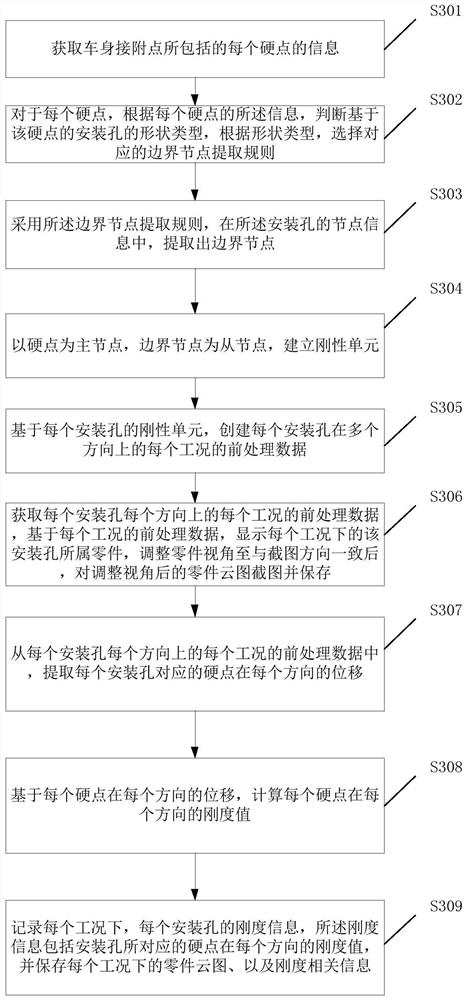
[0070] Such as image 3 Shown is a working flow chart of a method for extracting the stiffness result of the attachment point of the vehicle body according to one embodiment of the present application, including:

[0071] Step S301, obtaining the information of each hard point included in the body attachment point;

[0072] Step S302, for each hard point, according to the information of each hard point, determine the shape type of the installation hole based on the hard point, and select the corresponding boundary node extraction rule according to the shape type;

[0073] Step S303, using the boundary node extraction rule to extract boundary nodes from the node information of the installation hole;

[0074] Step S304, using the hard point as the master node and the boundary node as the slave node to establish a rigid unit;

[0075] Step S305, based on the rigid unit of each mounting hole, create pre-processing data of each working condition of each mounting hole in multiple ...

Embodiment 3

[0111] Such as Figure 7 Shown is a working flow chart of a method for extracting the stiffness result of the attachment point of the vehicle body according to one embodiment of the present application, including:

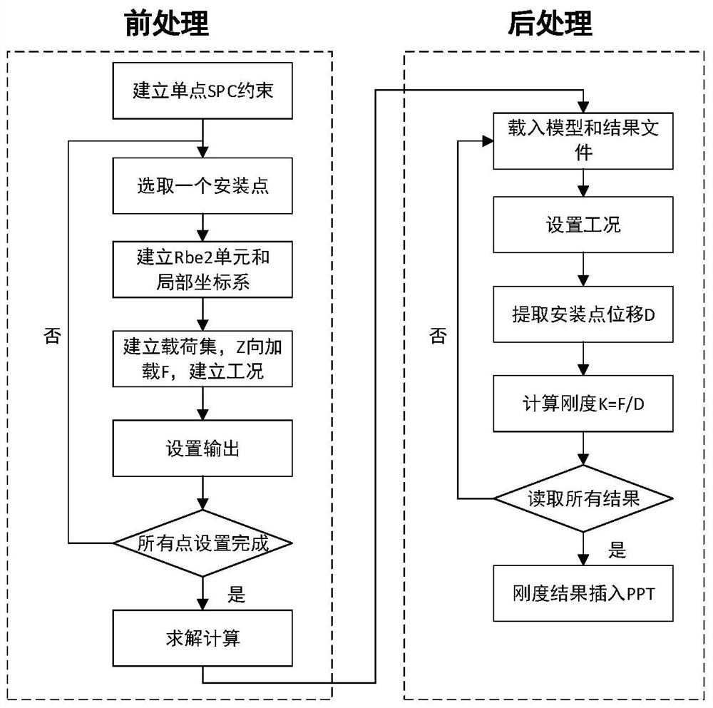
[0112] Step S701, open Hypermesh, import the body model, including the hard point geometry file of the attachment point, and run the pre-processing module;

[0113] Step S702, select all hard points of attachment points that need to be calculated;

[0114] Step S703, respectively setting the load size in the X, Y, and Z directions;

[0115] Step S704, establishing a rigid unit of the Washer layer with mounting holes;

[0116] Step S705, setting up X, Y, Z loads and loading conditions;

[0117] Step S706, submitting to the solver for calculation;

[0118] Step S707, running the post-processing module;

[0119] Step S708, calculating the stiffness of each working condition, and saving Excel;

[0120] Step S709, only displaying the part where the mounting hole i...


PUM


Abstract

The invention discloses a vehicle body attachment point rigidity result extraction method, electronic equipment and a storage medium. The method comprises the steps: searching a boundary node of an installation hole based on each hard point according to the information of each hard point, and constructing a rigid unit related to the installation hole based on the boundary node of the installationhole; creating preprocessing data of each mounting hole under each working condition in multiple directions; acquiring pretreatment data of each working condition in each direction of each mounting hole, displaying a part cloud picture of the part to which the mounting hole belongs under each working condition based on the pretreatment data of each working condition, and performing screenshot on the part cloud picture and storing; and based on the pre-processing data of each working condition in each direction of each mounting hole, rigidity information of each mounting hole under each workingcondition is calculated and stored. According to the method, the workload of engineers is reduced, all attachment points are selected in a framing mode at a time through the pretreatment part, namely, pretreatment and aftertreatment parts of all attachment points are achieved, and automatic adjustment and screenshot of the cloud picture view angle of each part are achieved.

Description

technical field [0001] The present application relates to the technical field related to automobiles, in particular to a method for extracting stiffness results of body attachment points and electronic equipment. Background technique [0002] Body attachment point stiffness is an important index affecting the NVH performance of the vehicle, and is an important content of Computer Aided Engineering (CAE) analysis in the process of automotive product development. Among them, NVH is noise Noise, vibration Vibration, and Harshness, which are important performances to measure the ride comfort of a car. Computer-aided engineering is an analysis method that uses computer software to assist in the analysis of structural mechanical properties of complex projects and products. [0003] Such as figure 1 Shown is the working flow chart of the prior art method for analyzing the results of attachment point stiffness. Among them, for the work of establishing a rigid unit (Rbe2 unit) at ...

Claims


Application Information

Patent Timeline
IPC IPC(8): G06F30/23G06F30/15G06F119/14
CPCG06F30/15G06F30/23G06F2119/14
Inventor 熊海林周泽傅君君
Owner EVERGRANDE NEW ENERGY AUTOMOTIVE INVESTMENT HLDG GRP CO LTD
Why Eureka
Try Eureka