
Multifunctional high-efficiency heat dissipation device applied to computer

A heat-dissipating device and high-efficiency technology, applied in the computer field, can solve the problems of incomplete heat dissipation, clogging of filter plates, and insufficient utilization of heat.

Pending Publication Date: 2020-10-23
HENAN UNIV OF CHINESE MEDICINE
View PDF11 Cites 1 Cited by
  • Summary
  • Abstract
  • Description
  • Claims
  • Application Information

AI Technical Summary

Problems solved by technology

[0003] The main box is installed with hardware such as program running storage elements and solid-state hard drives. During its operation, a large amount of heat will be generated. The traditional way is to realize the heat dissipation process through the cooling holes, and the heat generated is directly discharged. Going out, this method not only does not dissipate heat completely, but also in the process of long-term use, a large amount of dust will accumulate on the cooling net, which will easily cause the blockage of the filter plate, and at the same time, the heat emitted by it cannot be fully utilized, resulting in waste of heat energy. For this reason, we propose a multi-functional and high-efficiency cooling device for computer applications to solve the above-mentioned problems

Method used


Image

  • Multifunctional high-efficiency heat dissipation device applied to computer
  • Multifunctional high-efficiency heat dissipation device applied to computer
  • Multifunctional high-efficiency heat dissipation device applied to computer

Examples


Embodiment Construction

[0022] The following will clearly and completely describe the technical solutions in the embodiments of the present invention with reference to the accompanying drawings in the embodiments of the present invention. Obviously, the described embodiments are only some, not all, embodiments of the present invention.

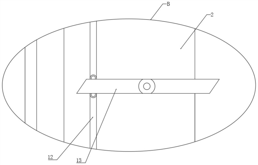
[0023] refer to Figure 1-5 , a multifunctional and high-efficiency cooling device for computer applications, comprising a box body 1 and a power element 6, the power element 6 is fixedly installed on the inner side wall of the box body 1, and a through hole 2 is opened on the side wall of the box body 1, and the through hole 2. A cleaning plate 9 is fixed inside, and a linkage mechanism is installed on the side wall of the through hole 2. The linkage mechanism includes a rotating plate 13 that is rotatably connected to the rear side wall of the through hole 2. The rotating plates 13 are rotatably connected by a connecting rod 12. , the upper and lower ends of the pl...


PUM


Abstract

The invention discloses a multifunctional high-efficiency heat dissipation device applied to a computer, and relates to the technical field of computers; the device comprises a box body and power elements; the power elements are fixedly mounted on the inner side wall of the box body; a through hole is formed in the side wall of the box body; a cleaning plate is fixedly mounted in the through hole;a linkage mechanism is rotationally mounted on the side wall of the through hole; an air draft mechanism is mounted on the inner side wall of the box body; a dust suction box is fixedly mounted on the outer side wall of the box body; a sliding pipe is fixedly mounted in the dust suction box; the end part of the box body is fixedly connected with a heating head; an adjusting mechanism is mounted in the heating head; a ventilation groove is formed in the side wall of the box body in a penetrating mode, a filter plate is installed in the ventilation groove, a sliding groove communicating with the ventilation groove is formed in the inner top of the ventilation groove; the negative pressure effect is achieved through an air draft mechanism, and the dustproof plate is cleaned while heat dissipation of power elements in the box body is achieved.

Description

technical field [0001] The invention relates to the technical field of computers, in particular to a multifunctional and high-efficiency cooling device for computer applications. Background technique [0002] The computer has a complete system to complete various tasks. This system is composed of two parts: hardware system and software system. Both are indispensable. Computer equipment is a variety of machinery used to assist the normal operation of the computer. Screen; [0003] The main box is installed with hardware such as program running storage elements and solid-state hard drives. During its operation, a large amount of heat will be generated. The traditional way is to realize the heat dissipation process through the cooling holes, and the heat generated is directly discharged. Going out, this method not only does not dissipate heat completely, but also in the process of long-term use, a large amount of dust will accumulate on the cooling net, which will easily cause...

Claims


Application Information

Patent Timeline
Patent Type & Authority Applications(China)
IPC IPC(8): G06F1/20B08B1/00B08B1/02
CPCG06F1/20G06F2200/202B08B1/12B08B1/20
Inventor 李光
Owner HENAN UNIV OF CHINESE MEDICINE
Learn More