
Detection device and method of space debris ranging and imaging composite optical system

A technology for optical systems and space debris, applied in the direction of using optical devices, measuring devices, testing optical performance, etc., can solve problems such as reducing system accuracy indicators, damage, and optical component offset

Inactive Publication Date: 2020-10-23
CHANGCHUN UNIV OF SCI & TECH
View PDF6 Cites 4 Cited by
  • Summary
  • Abstract
  • Description
  • Claims
  • Application Information

AI Technical Summary

Problems solved by technology

Usually, for a multi-functional complex imaging system for space debris ranging, it is necessary to use a variety of detection equipment for joint detection and calibration, in which repeated disassembly and transportation between multiple laboratories are unavoidable, and repeated Due to adverse vibration and shock of the system under inspection during the process, the optical components may be shifted, reducing the accuracy index of the system or even causing damage and making it unusable
At present, there is no special device that can meet the detection and calibration requirements of the compound optical system for space debris ranging and imaging.

Method used


Image

  • Detection device and method of space debris ranging and imaging composite optical system
  • Detection device and method of space debris ranging and imaging composite optical system
  • Detection device and method of space debris ranging and imaging composite optical system

Examples


Embodiment 1

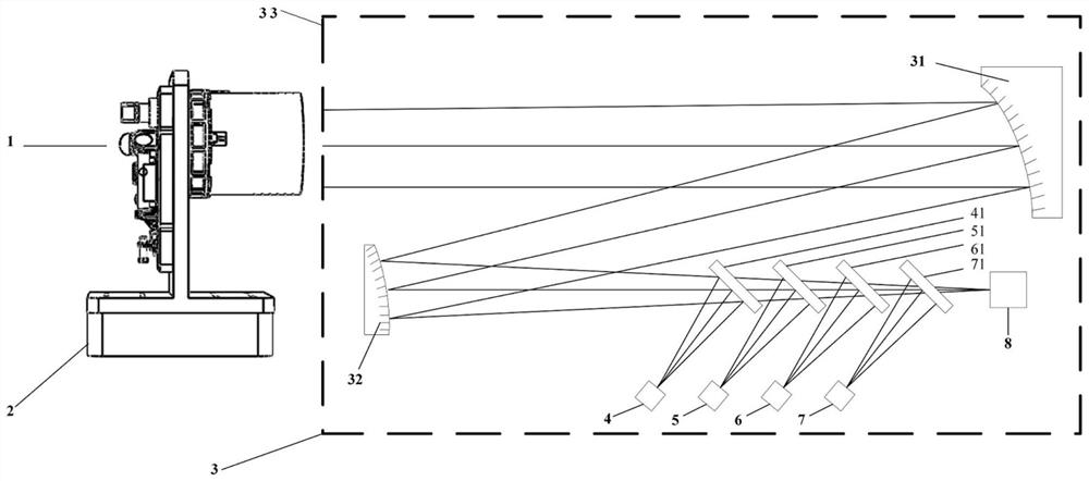
[0085] A detection device of a composite optical system for ranging and imaging of space debris is the same as the above, a detection device using a composite optical system for ranging and imaging of space debris is used to carry out the fine tracking system 21 in the composite optical system for ranging and imaging of space debris The method for assembling and calibrating is the same as above, the difference is that in step 3, the theoretical optical axis position of the fine tracking system 21 in the compound optical system 1 is calculated, and the CCD detection camera 10 in the compound optical system 1 is transmitted to the fine tracking system 21 Theoretical optical axis position, at this moment, the deviation between the light spot position on the CCD detection camera 10 and the cross center position of the CCD detection camera 10 is the installation error;

[0086] In Step 4, the parallel light emitted by the collimator focal plane assembly 8 finally enters the CCD dete...

Embodiment 2

[0089] A detection device of a composite optical system for space debris ranging and imaging is the same as above, a detection device using a composite optical system for ranging and imaging of space debris detects the single-photon ranging emission in the composite optical system for ranging and imaging of space debris The method for installing and calibrating the unit 16, the specific steps are the same as above, the difference is that in step 3, the theoretical optical axis position of the single-photon ranging emitting unit 16 in the compound optical system 1 is calculated, and the space debris ranging imaging compound optical system 1 The CCD detection camera 10 is transmitted to the theoretical optical axis position of the single-photon ranging emission unit 16, and now the deviation between the spot position on the CCD detection camera 10 and the cross center position of the CCD detection camera 10 is an installation error;

[0090] Step 4 The parallel light emitted by t...

Embodiment 3

[0093] A detection device of a composite optical system for space debris ranging and imaging is the same as the above, a detection device using a composite optical system for ranging and imaging of space debris detects the ranging receiving unit 15 in the composite optical system for ranging and imaging of space debris The method for installing and calibrating, the specific steps are the same as above, the difference is that in step 3, the theoretical optical axis position of the ranging receiving unit 15 in the space debris ranging and imaging compound optical system 1 is calculated, and the CCD detection camera in the compound optical system 1 is 10 is transmitted to the theoretical optical axis position of the distance measuring receiving unit 15, at this time, the deviation between the spot position on the CCD detection camera 10 and the cross center position of the CCD detection camera 10 is the installation error;

[0094] In Step 4, the parallel light emitted by the foca...


PUM


Abstract

The invention belongs to the technical field of optical detection and assembly and calibration, and particularly relates to a detection device and method of a space debris ranging and imaging composite optical system. The device comprises a five-dimensional precision assembling and calibrating platform and a multi-focal-plane collimator which are used for fixing a space debris ranging and imagingcomposite optical system, and the five-dimensional precision assembling and calibrating platform and the multi-focal-plane collimator are installed at the two ends of an optical platform in a horizontal state respectively; precise assembly and calibration and comprehensive index special detection can be carried out on each component in the space debris ranging and imaging composite optical system;detected equipment does not need to be changed into a site and does not need to be repeatedly disassembled and assembled; and detection indexes are comprehensive, risks of transportation and repeateddisassembly and assembly are avoided, assembly and calibration precision and efficiency are improved, characteristics of the multi-focal-plane collimator are utilized, a work flow that multiple detection devices are needed for combined detection in the past is solved, detection and high-precision assembly and calibration of multiple indexes are performed through the same device, work efficiency is greatly improved, and cost lasers are saved.

Description

technical field [0001] The invention belongs to the technical field of optical detection and calibration, and in particular relates to a detection device and method of a compound optical system for ranging and imaging of space debris. Background technique [0002] With the continuous improvement of the requirements for space debris detection, the space debris detection system is gradually developing towards integration and multi-function. Among them, the high-precision, high-efficiency calibration and fast detection methods for complex optical paths in space debris ranging and imaging compound optical systems are particularly important. Usually, for a multi-functional complex imaging system for space debris ranging, it is necessary to use a variety of detection equipment for joint detection and calibration, in which repeated disassembly and transportation between multiple laboratories are unavoidable, and repeated Due to adverse vibration and shock of the system under inspe...

Claims


Application Information

Patent Timeline
Patent Type & Authority Applications(China)
IPC IPC(8): G01M11/00G01M11/02G01S7/497G01B11/00G01B11/24G01C1/00G01N21/25
CPCG01B11/00G01B11/24G01C1/00G01M11/00G01M11/02G01N21/25G01S7/497
Inventor 李响白东伟高亮安岩宋延嵩
Owner CHANGCHUN UNIV OF SCI & TECH
Learn More