
A kind of optical axis angle adjustment method

A technology of optical axis and angle, which is applied in determining the optical axis, testing optical performance, determining the position of the lens, etc., can solve the problems of high stress and poor precision, and achieve the goal of improving stability, improving efficiency of installation and calibration, and improving adjustment accuracy Effect

Active Publication Date: 2021-09-17
LUOYANG INST OF ELECTRO OPTICAL EQUIP OF AVIC
View PDF0 Cites 0 Cited by
  • Summary
  • Abstract
  • Description
  • Claims
  • Application Information

AI Technical Summary

Problems solved by technology

[0003] The purpose of the present invention is to provide a method for adjusting the optical axis angle to solve the problems of large stress and poor precision caused by repeated trial installation of gaskets

Method used


Image

  • A kind of optical axis angle adjustment method
  • A kind of optical axis angle adjustment method
  • A kind of optical axis angle adjustment method

Examples


Embodiment 1

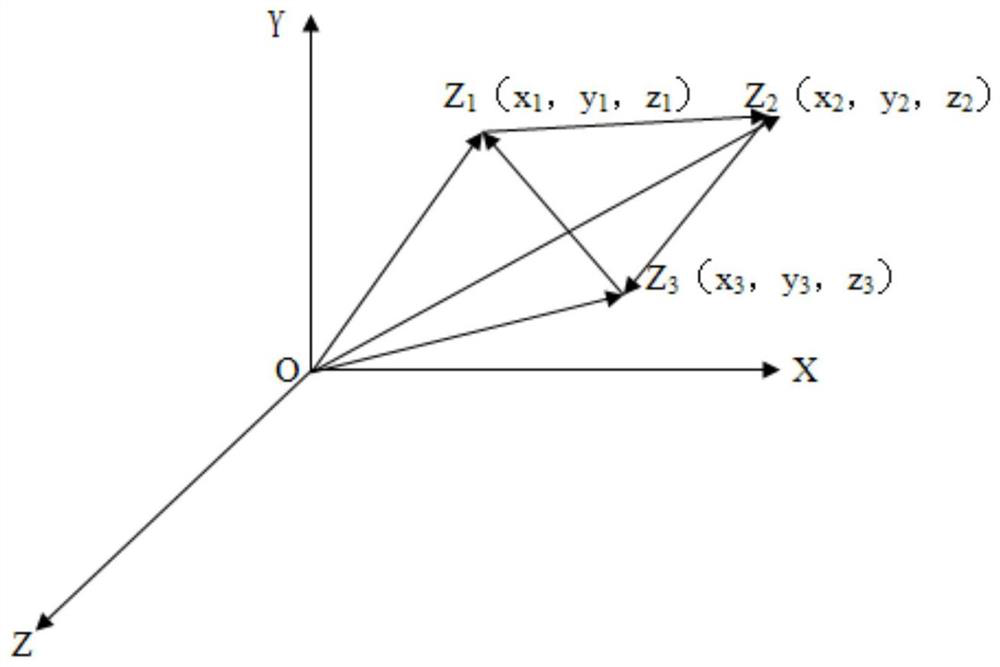
[0036] The azimuth deviation of the laser receiving optical axis is -1', the pitch deviation is -1.5', and the coordinates of the three spacers are as follows Figure 4 As shown, they are O(0, 0, 0), z1 (-42.5, 162.5, z1), z2 (219, 145, z2), z3 (219, 3.5, z3), and substitute into equations (1), ( 2), (3), can be solved

[0037] z1=0.029mm

[0038] z2 = 0.063mm

[0039] z3 = 0.032mm

Embodiment 2

[0041] The azimuth deviation of the laser receiving optical axis is -30", the pitch deviation is -1.5', and the coordinates of the 6 spacers are as follows Figure 5 As shown, they are O(0, 0, 0), z1 (0, 307.5, z1), z2 (230.4, 307.5, z2), z3 (0, 128.2, z3), z4 (230.4, 128.2, z4), Substituting z5(230.4, 0, z5) into equations (1), (2), (3), the solution is

[0042] z1=0.067mm

[0043] z2 = 0.084mm

[0044] z3 = 0.030mm

[0045] z4=0.045mm

[0046] z5 = 0.017 mm.


PUM


Abstract

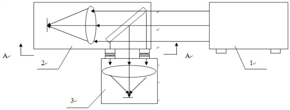
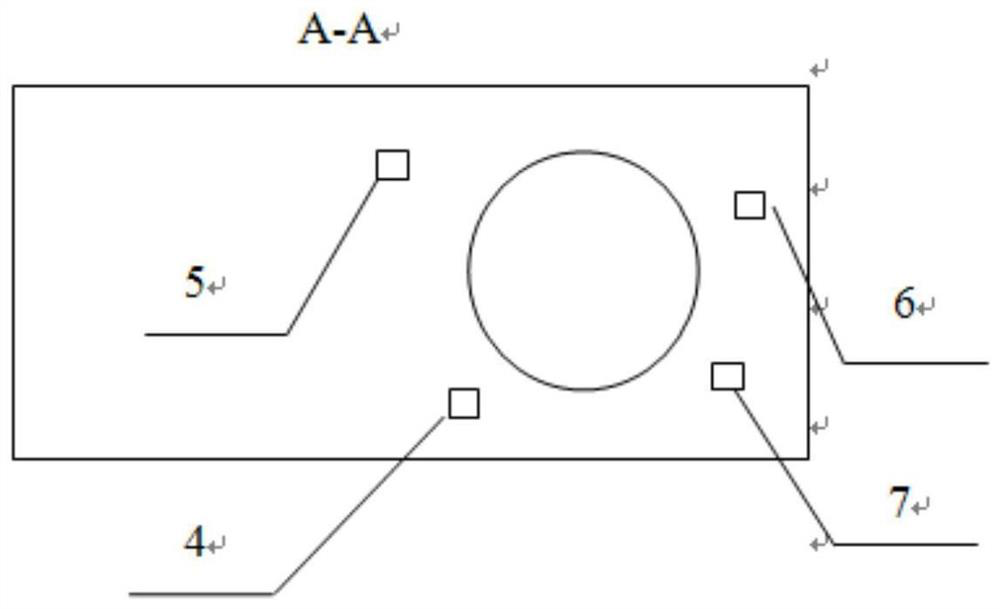
The invention relates to an optical axis angle adjustment method belonging to the technical field of precision optical-mechanical installation and calibration, and relates to an optical axis adjustment method. The adjustment method is as follows: adjusting the azimuth and pitch angle of an infrared target source The optical axis of the source 1 is parallel to the infrared component 2; the azimuth angle deviation α and the pitch angle deviation β of the optical axis of the laser receiving component 3 are detected; the thickness of the three spacers can be calculated according to the formula; the invention adopts an innovative According to the test results of the optical axis deviation, the thickness of each gasket is accurately calculated, and the precise adjustment of the optical axis is realized. The method of the invention has high precision, high efficiency and stable optical axis.

Description

technical field [0001] The invention belongs to the technical field of precision optical machine adjustment, and relates to an optical axis adjustment method. Background technique [0002] The airborne photoelectric detection and tracking system is used for target detection, tracking and ranging, and can guide laser-guided bombs to attack the target. The airborne photoelectric detection and tracking system includes infrared components, laser receiving components and laser emitting components. In order to improve the aiming accuracy and weapon strike accuracy, it is often required that the optical axes of the laser receiving component, laser emitting component and infrared component be parallel, and the error is within 10” , the processing accuracy of the parts cannot be guaranteed, and the optical axes of the above three components need to be corrected with gaskets. The previous calibration method is: firstly adjust the azimuth and elevation angle of the infrared target sour...

Claims


Application Information

Patent Timeline
Patent Type & Authority Patents(China)
IPC IPC(8): G01M11/02
CPCG01M11/0221
Inventor 董续勇张华锋王鹏赵艳平高鹏涛
Owner LUOYANG INST OF ELECTRO OPTICAL EQUIP OF AVIC
Learn More