Full-automatic pneumatic control device

A fully automatic, component-controlled technology, applied in valve devices, valve operation/release devices, engine components, etc., to solve problems such as poor functionality and reliability, incompleteness, and difficulty in draining condensed water.

Pending Publication Date: 2020-10-23
QINGHUAN TUODA (SUZHOU) ENVIRONMENTAL TECH CO LTD
View PDF6 Cites 0 Cited by
  • Summary
  • Abstract
  • Description
  • Claims
  • Application Information

AI Technical Summary

Problems solved by technology

[0027] The purpose of the present invention is to provide a fully automatic pneumatic control device to solve the problems in the prior art that the condensed water i...

Method used


Image

  • Full-automatic pneumatic control device
  • Full-automatic pneumatic control device
  • Full-automatic pneumatic control device

Examples


Embodiment Construction

[0078] Below in conjunction with specific embodiment, content of the present invention is described in further detail:

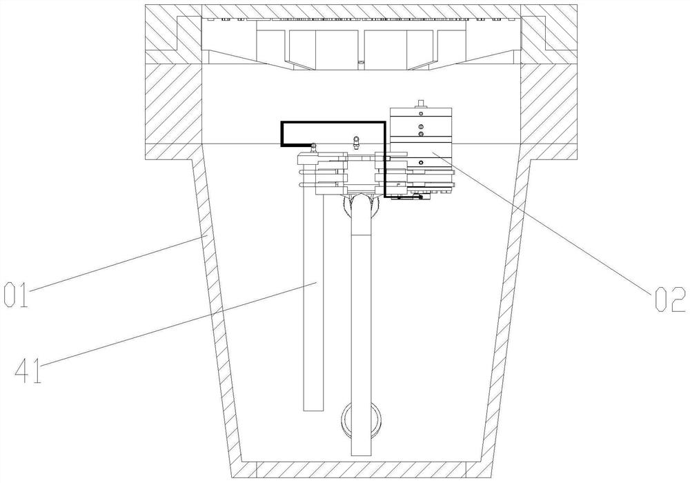
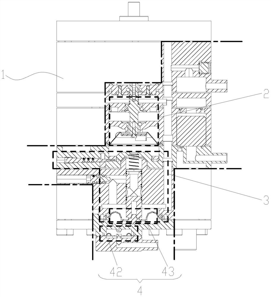
[0079] Such as figure 1 As shown, a fully automatic pneumatic control device is installed in the vacuum well 01, and is used to transport the sewage in the vacuum well 01 to the downstream vacuum collection pipeline network, which is figure 1 Parts labeled "02", such as figure 2 As shown, its structure includes a housing 1, an executive assembly 2 and a power assembly 3 installed in the housing 1, a control assembly 4 that triggers the power assembly 3 to drive the execution assembly 2 to work; the execution assembly 2, the power assembly 3 and the control assembly 4 Distributed sequentially from top to bottom.

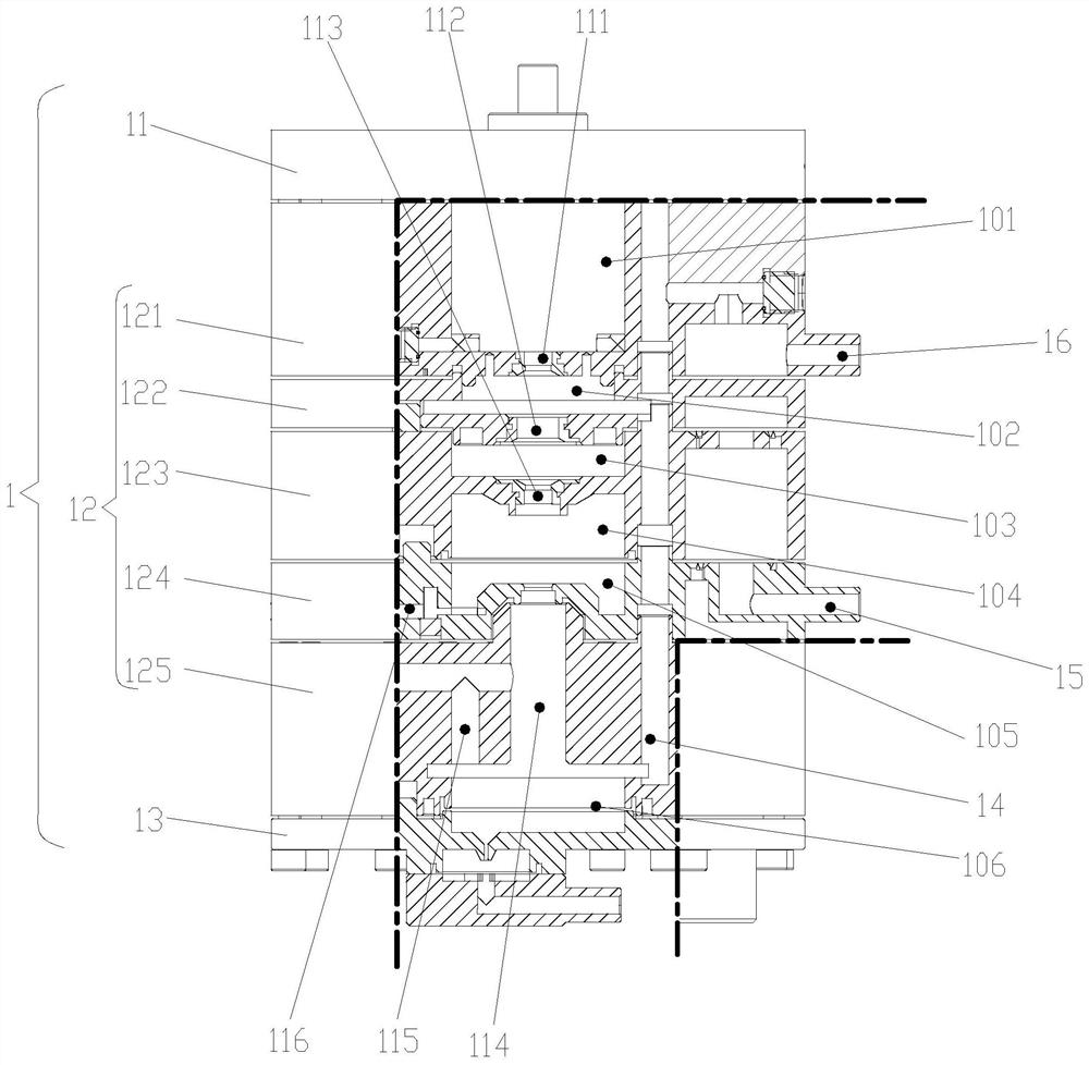
[0080] Such as image 3 As shown, the housing 1 includes an upper housing 11, a middle housing 12 and a lower housing 13 arranged sequentially from top to bottom. In order to facilitate the processing of each space inside the middle housing 12, ...


PUM


Abstract

The invention relates to a full-automatic pneumatic control device. The full-automatic pneumatic control device comprises a shell, an execution assembly, a power assembly and a control assembly, wherein the execution assembly and the power assembly are installed in the shell, and the control assembly triggers the power assembly to drive the execution assembly to work. The execution assembly, the power assembly and the control assembly are sequentially distributed from top to bottom. The execution assembly comprises a valve element assembly used for achieving on-off of air and vacuum. The powerassembly comprises a needle valve assembly used for achieving delayed closing and a sliding valve assembly used for achieving rapid opening. The control assembly comprises a liquid level pressure sensor, a pressure stabilizing and buffering unit and a kinetic energy conversion unit. The device is mainly composed of three core assemblies including the execution assembly, the power assembly and thecontrol assembly, and compactness and reliability of structural design can be achieved; and the space formed inside has active, reliable and effective water collection and drainage technology and structure, and the reasonable distribution pipeline design inside is small in resistance and high in efficiency.

Description

technical field [0001] The invention relates to the technical field of vacuum sewage valve control system in the continuous collection, temporary storage and periodic transportation system of vacuum sewage. It is a temporary sewage collection device for sewage discharge, and can transport the sewage in its sewage collection device to the downstream vacuum collection pipeline network, and adopts the differential pressure drive control method, that is, the pneumatic control method for control, and its components mainly include vacuum sewage discharge Valve, sewage cavity, equipment cavity, well cover, manual ball valve, gravity sewage inlet pipeline, sewage discharge pipeline connected to the downstream vacuum collection pipeline network, sewage suction pipeline; for the vacuum sewage valve control system in the vacuum well, the present invention is It particularly relates to a fully automatic pneumatic control device. Background technique [0002] In the field of vacuum dome...

Claims


Application Information

Patent Timeline
IPC IPC(8): F16K31/126
CPCF16K31/1268
Inventor 崔利兴邓永峰黄森辰
Owner QINGHUAN TUODA (SUZHOU) ENVIRONMENTAL TECH CO LTD
Why Eureka
Try Eureka