Noise reduction and impurity removal pressure reduction regulating valve

A decompression regulating valve and noise reduction technology, applied in the direction of lift valve, valve detail, valve device, etc., can solve the problems of high noise, accumulation of impurities, etc.

Active Publication Date: 2020-10-23
ZHEJIANG ZHONGDE AUTOMATIC CONTROL VALVE
View PDF10 Cites 0 Cited by
  • Summary
  • Abstract
  • Description
  • Claims
  • Application Information

AI Technical Summary

Problems solved by technology

[0005] In view of the above problems, the present invention provides a noise-reducing and impurity-removing pressure-reducing regulating valve, which uses the traditional one-piece spool to be separately arranged, so that when the outer spool is lowered and closed, the inner spool will enter the water flow. The channel is connected to the decompression chamber, so that the fluid medium enters the decompression chamber to reduce the pressure difference between the upper and lower surfaces of the outer valve core. The fluid medium in the decompression chamber flows to the water outlet channel to compensate the gap at the end of the water outlet channel, thereby eliminating the eddy current phenomenon. When the valve core of the single-seat valve is lifted and opened, it is easy to generate eddy current phenomenon at the water outlet channel. The noise is loud, and the single-seat valve is easy to accumulate impurities at the root of the water outlet after it is closed for a long time

Method used


Image

  • Noise reduction and impurity removal pressure reduction regulating valve
  • Noise reduction and impurity removal pressure reduction regulating valve
  • Noise reduction and impurity removal pressure reduction regulating valve

Examples


Embodiment 1

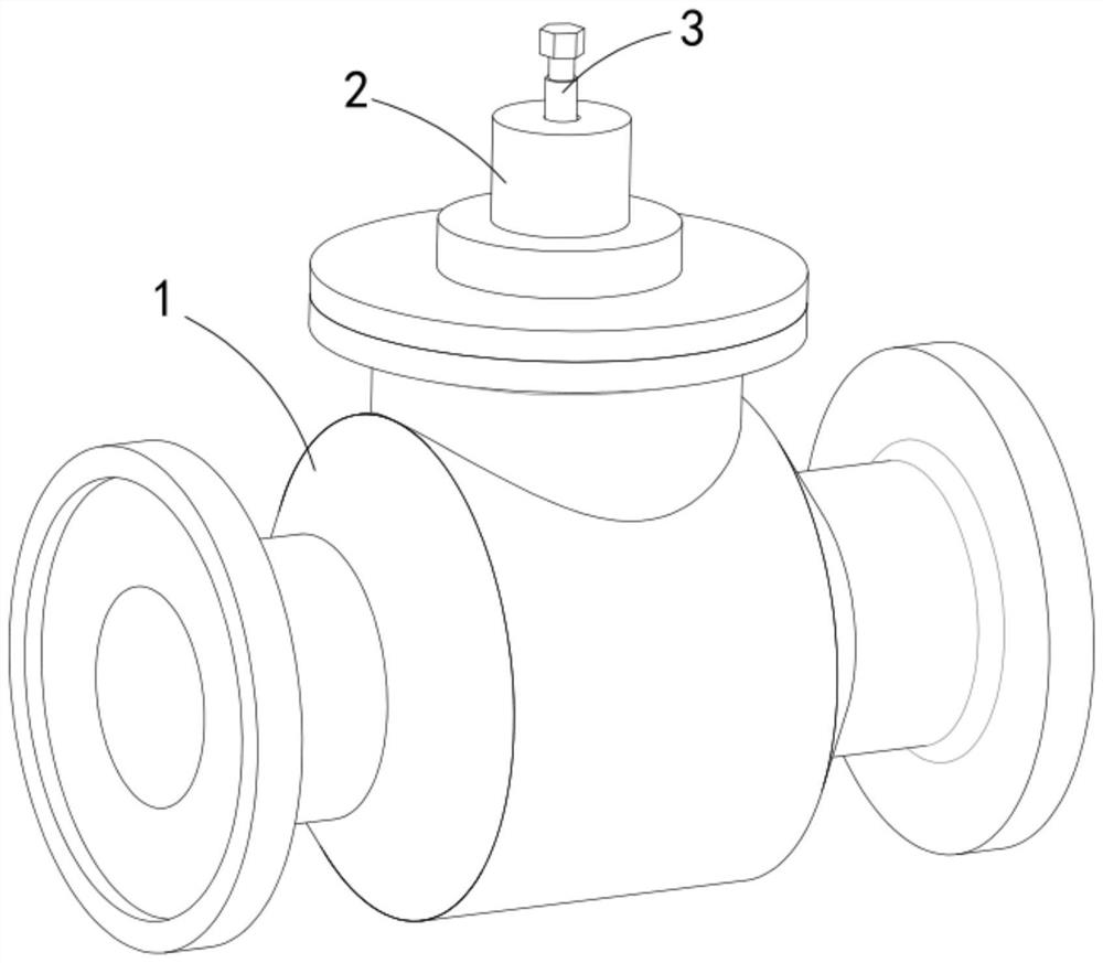
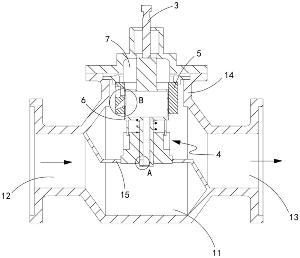
[0045] like figure 1 and 2 As shown in the figure, a noise reduction and impurity decompression regulating valve includes a valve body 1, a valve cover 2 and a valve stem 3. The valve body 1 is provided with a valve cavity 11, a water inlet channel 12, a water outlet channel 13 and a valve. The valve core installation port 14, the valve seat 15 is installed in the valve cavity 11, the valve cover 2 is sealed and installed on the valve core installation port 14, the valve stem 3 is slidably arranged in the valve cover 2, and also include:

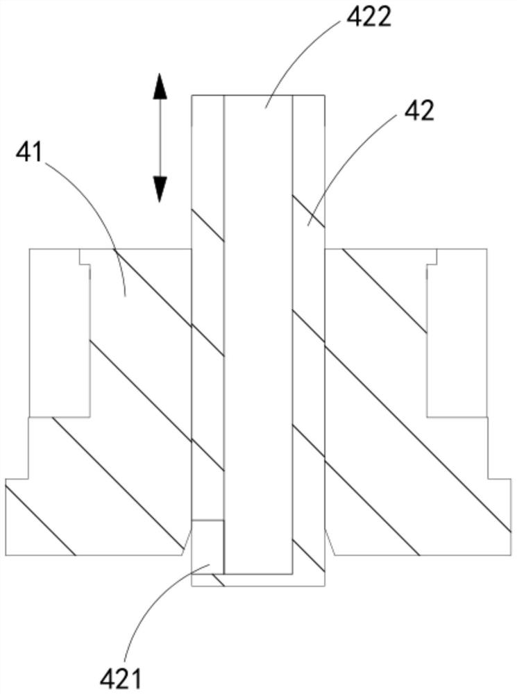
[0046]Combined spool mechanism 4, the combined spool mechanism 4 moves up and down along the axial direction of the core installation port 14 to cooperate with the valve seat 15 to open or close the gate, which includes a hollow outer spool 41 and sleeved on the valve core The inner spool 42 inside the outer spool 41 and vertically slides along the outer spool 41, the outer spool 41 and the inner spool 42 are spliced ​​to form a complete s...


PUM


Abstract

The invention provides a noise reduction and impurity removal pressure reduction regulating valve. The noise reduction and impurity removal pressure reduction regulating valve comprises a valve body,a valve cover and a valve rod. A valve cavity, a water inlet flow channel, a water outlet flow channel and a valve core mounting opening are formed in the valve body. A valve seat is mounted in the valve cavity. The valve cover is mounted on the valve core mounting opening in a sealed manner. The valve rod is slidably arranged in the valve cover. The noise reduction and impurity removal pressure reduction regulating valve further comprises a combined valve core mechanism, a guide lining and a piston unit. According to the noise reduction and impurity removal pressure reduction regulating valve, a traditional integrated valve core is arranged in a split manner, an inner valve core makes the water inlet flow channel communicated with a pressure reduction cavity when an outer valve core performs descending switching-on, and a fluid medium enters the pressure reduction cavity to reduce the pressure difference of the upper end face and the lower end face of the outer valve core; when the outer valve core performs ascending switching-off, a backflow unit is communicated with the pressure reduction cavity and the water outlet flow channel; and the fluid medium in the pressure reduction cavity flows to the water outlet flow channel and is used for compensating for the clearance of the end portion of the water outlet flow channel, so that the vortex phenomenon is eliminated, and impurities at the root of the water outlet flow channel are removed.

Description

technical field [0001] The invention relates to the technical field of valves, in particular to a decompression regulating valve for noise reduction and impurity removal. Background technique [0002] The opening and closing part of the single-seat valve is the valve core. The valve core of the single-seat valve moves linearly with the valve stem to open or close the gate. When the valve core is lifted and closed, the valve core is subjected to the pressure of the fluid medium on one end face. There will be a large pressure on it, which needs the valve core to resist, and when the valve core of the single-seat valve is lifted and opened, it is prone to eddy currents at the outlet channel, which is noisy and easy to accumulate impurities here. [0003] The patent document with the patent number of CN200810244539.6 discloses a single-seat regulating valve that can withstand a large pressure difference, including: a valve body, a valve cover and a valve stem, and the valve body...

Claims


Application Information

Patent Timeline
IPC IPC(8): F16K1/00F16K1/32F16K1/36F16K47/02F16K47/04
CPCF16K1/00F16K1/32F16K1/36F16K47/02F16K47/04
Inventor 王辉骆群华陈维熊杨亮肖祥忠王阳
Owner ZHEJIANG ZHONGDE AUTOMATIC CONTROL VALVE
Why Eureka
Try Eureka