


Quick Research
Generate reliable direction feasibility study reports for your R&D in just a few steps.

Technical Q&A
Discover and master advanced knowledge NOW. Basics, ideas, possibilities, all at once.

Find Solutions
As an expert in R&D theories, this can generate solutions to your technical problems instantly.

Evaluate Feasibility
Analyze your overall solution with one click, know your potential R&D risks in advance.

Monitor Landscape
Get weekly tech updates, stay abreast of the latest tech innovations and key insights.
Safety management method of energy isolation
A safety management and energy technology, applied in instruments, display devices, building locks, etc., can solve problems such as equipment opening, accidental release of energy, injury to equipment maintenance operators, etc., to avoid misoperation, improve stability, and improve connection stability. sexual effect
- Summary
- Abstract
- Description
- Claims
- Application Information
AI Technical Summary
Problems solved by technology
Method used
Image

Examples
Embodiment 1
[0038] A safety management method for energy isolation, comprising the following steps:
[0039] Step 1: Before the maintenance of the equipment, the maintenance personnel shall handle the written power-off approval. After the approval is passed, the electrician shall carry out the power-off operation of the power supply and the control circuit, and confirm that the power supply drawer is pulled out or the switch is turned off, and the equipment is in the "stop" state. "Location.
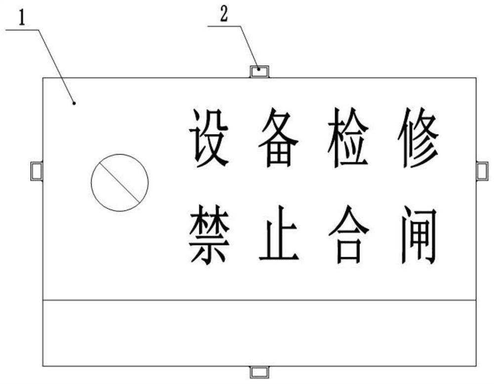
[0040] Step 2: After the electrician confirms that the equipment has been powered off, hang a special warning sign on the power supply drawer or switch in the electrical room, and the special warning sign is marked with warning words such as "equipment maintenance, prohibit closing".
[0041] Step 3: The maintenance personnel and the electrician lock the pull-out drawer or the switch respectively, and the two locks have different lock cylinders, that is, the maintenance personnel hold the key Ⅰ, and...
Embodiment 2
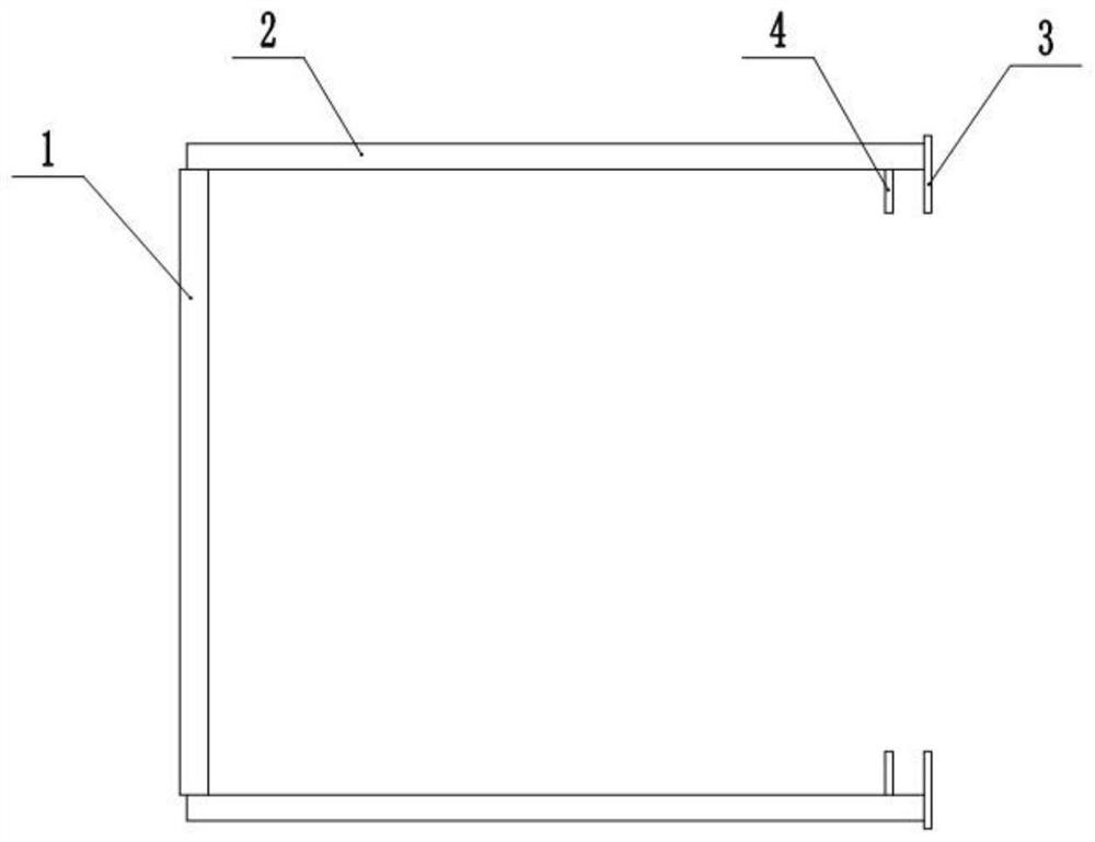
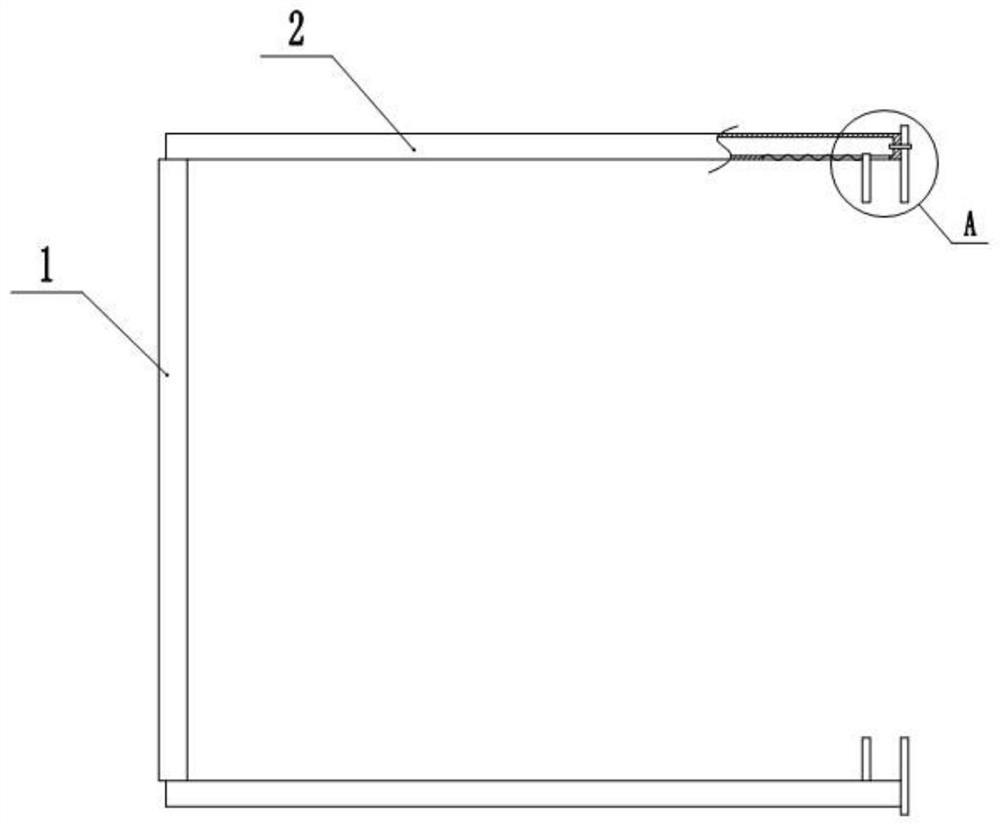
[0048] Embodiment 2 is basically as attached image 3 with Figure 4 Shown:
[0049]The difference from Embodiment 1 is that the second connecting plate 4 is slidably connected to the horizontal bar 2, and the specific setting is: a chute 6 is opened along the length direction of the horizontal bar 2, and the second connecting plate 4 is slidably connected in the chute 6 , the end of the second connecting plate 4 and the chute 6 away from the first connecting plate 3 is fixed with a compression spring 7, initially the second connecting plate 4 is close to the first connecting plate 3, in addition, in order to improve stability, the first connecting plate 3 and the second connecting plate 4 are both magnetic plates, and the first connecting plate 3 and the second connecting plate 4 attract each other. This can be applied to the sides of power supply drawers of different thicknesses.
PUM
| Property | Measurement | Unit |
|---|---|---|
| Length | aaaaa | aaaaa |
Abstract
Description
Claims
Application Information
 - R&D Engineer
- R&D Manager
- IP Professional
- Industry Leading Data Capabilities
- Powerful AI technology
- Patent DNA Extraction
Browse by: Latest US Patents, China's latest patents, Technical Efficacy Thesaurus, Application Domain, Technology Topic, Popular Technical Reports.
© 2024 PatSnap. All rights reserved.Legal|Privacy policy|Modern Slavery Act Transparency Statement|Sitemap|About US| Contact US: help@patsnap.com