Groundwater observation well pipe and observation method for geotechnical investigation and surveying

A technology for engineering survey and observation wells, which is applied in infrastructure engineering, on-site foundation soil survey, construction, etc., and can solve the problems of blocked well pipes, rough separation means, and high engineering cost.

Pending Publication Date: 2020-10-23
WUHAN SURVEYING GEOTECHN RES INST OF MCC
View PDF0 Cites 1 Cited by
  • Summary
  • Abstract
  • Description
  • Claims
  • Application Information

AI Technical Summary

Problems solved by technology

In the existing observation method, the well pipe is installed joint by joint, and it is necessary to repeatedly align the joints, which is easy to collapse the hole. Since the side wall of the well pipe needs to be backfilled with filter material and clay balls, the clay particles are easy to adhere to the filter pipe of the well pipe and block the well. tubes, resulting in distortion of the water level observation results, so it needs to be cleaned and cleaned several times; and the existing measurement methods are relatively rough for different groundwater separation methods, which will also lead to the observed water level distortion
In addition, the existing observation methods can only observe the water level of one aquifer. When there are two aquifers in the site and need to observe the groundwater level, two sets of observation wells need to be built, and the project cost is relatively high.

Method used


Image

  • Groundwater observation well pipe and observation method for geotechnical investigation and surveying
  • Groundwater observation well pipe and observation method for geotechnical investigation and surveying
  • Groundwater observation well pipe and observation method for geotechnical investigation and surveying

Examples


Embodiment Construction

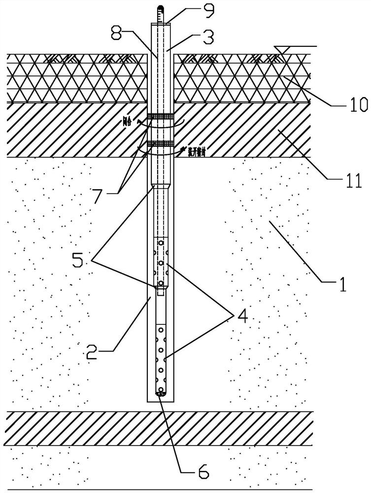
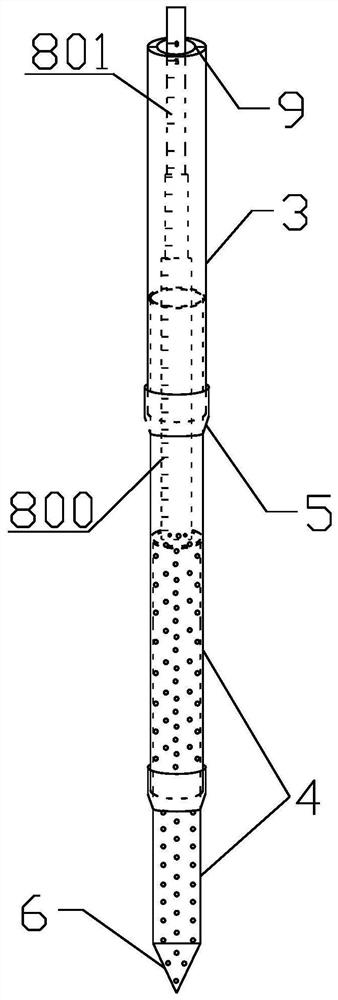
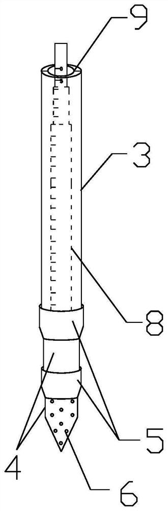
[0037] The present invention will be further described below in conjunction with drawings and embodiments. attached Figure 1 to Figure 7 The drawings for the embodiments are drawn in a simplified manner and are only used for the purpose of clearly and concisely illustrating the embodiments of the present invention. The following technical solutions shown in the drawings are specific solutions of the embodiments of the present invention, and are not intended to limit the scope of the claimed invention. Based on the embodiments of the present invention, all other embodiments obtained by persons of ordinary skill in the art without creative efforts fall within the protection scope of the present invention.

[0038] In the description of the present invention, it should be understood that the orientations or positional relationships indicated by the terms "upper", "lower", "inner", "outer", "left", "right" etc. are based on those shown in the accompanying drawings. Orientation ...


PUM


Abstract

The invention provides a groundwater observation well pipe and an observation method for geotechnical investigation and surveying. The groundwater observation well pipe comprises an observation well hole, a telescopic well pipe, and telescopic push rods placed in the telescopic well pipe, wherein the telescopic well pipe comprises an outer layer solid wall pipe body and one or two or more telescopic perforated pipes in mutual sleeving connection; the end of the most outer layer telescopic rod of each telescopic push rod is connected with the most inner layer telescopic perforated pipe; the length of the outer layer solid wall pipe is greater than or equal to the distance between the openings of the observation well hole and the top surface of a water containing layer to be tested; and after the telescopic well pipe is mounted in the observation well hole, a rotary switching sealing ring is arranged outside the outer layer solid wall pipe body in a sleeving manner to realize sealing ofthe outer wall of the well pipe above the water containing layer to be tested and the hole wall of the observation well hole, and after the groundwater water level in the holes is stable, observationof the water level can be performed. Clay balls do not need to be backfilled, observation accuracy can be guaranteed, primary pipe sinking in place can be realized, the problem that the well pipe is mounted to cause subsidence of the hole wall can be solved, and the groundwater level can be observed in a layering manner.

Description

technical field [0001] The invention relates to the technical field of engineering geology and hydrogeological survey, in particular to a simple and effective groundwater observation well pipe and observation method for engineering survey. [0002] technical background [0003] In the process of engineering geology and hydrogeological investigation, it is very important to conduct water level observation and long-term monitoring of groundwater on the site. It involves dynamic evaluation of groundwater and anti-floating of foundation pits, which are important aspects of engineering construction. Site Groundwater sometimes has types such as upper stagnant water, phreatic water, and confined water, all of which require special observation holes for observation during surveying. [0004] The existing conventional groundwater observation method is to use a geological drilling rig to form a hole, then install and manufacture the well pipe, install the well pipe joint by joint, back...

Claims


Application Information

Patent Timeline
Patent Type & Authority Applications(China)
IPC IPC(8): E02D1/00
CPCE02D1/00E02D1/027
Inventor 王辉李亚威姚东珂罗丙圣丁洪元潘志军
Owner WUHAN SURVEYING GEOTECHN RES INST OF MCC
Why Eureka
Try Eureka