
Printing machine with heat dissipation assembly

A technology for heat dissipation components and printing machines, which is applied to printing machines, rotary printing machines, screen printing machines, etc., and can solve problems such as inconvenient adjustment, affecting the normal operation of printing machines, and insufficient to ensure normal heat dissipation of printing machines

Inactive Publication Date: 2020-10-23
王社
View PDF0 Cites 2 Cited by
  • Summary
  • Abstract
  • Description
  • Claims
  • Application Information

AI Technical Summary

Problems solved by technology

[0004] The purpose of the present invention is to provide a printing machine with a heat dissipation assembly, to solve the problem that the size of the heat dissipation hole of the heat dissipation assembly of the existing printing machine proposed in the background technology is fixed, which is inconvenient to adjust, and the printing machine is caused by the external environment. When the interior is overheated, it is not enough to ensure the normal heat dissipation of the printing machine, which will affect the normal operation of the printing machine, and it will be intruded by dust and water.

Method used

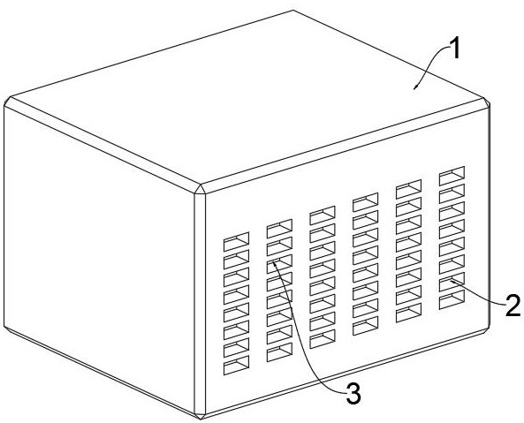

Image

  • Printing machine with heat dissipation assembly
  • Printing machine with heat dissipation assembly
  • Printing machine with heat dissipation assembly

Examples


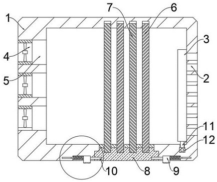
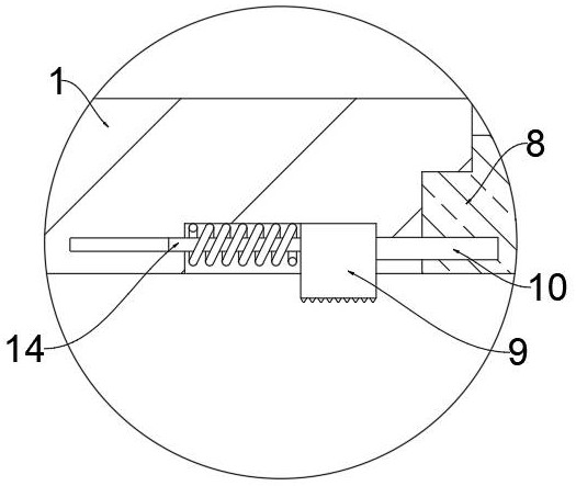
Embodiment Construction

[0027] The following will clearly and completely describe the technical solutions in the embodiments of the present invention with reference to the accompanying drawings in the embodiments of the present invention. Obviously, the described embodiments are only some, not all, embodiments of the present invention.

[0028] see Figure 1 to Figure 5, an embodiment provided by the present invention: a printing machine with a heat dissipation assembly, including a heat sink housing 1, a number of air ducts 5 are evenly arranged on the rear end surface of the heat sink housing 1, and the inside of the air duct 5 is fixedly installed There is a heat dissipation fan 4, and a movable bottom plate 8 is movably installed on the bottom surface of the outer casing 1 of the heat dissipation device. Two dust-proof plates 6 are uniformly installed above the movable bottom plate 8, and two moisture-absorbing plates 7 are installed in the middle of the two dust-proof plates 6. It can absorb the...


PUM


Abstract

The invention discloses a printing machine with a heat dissipation assembly. The printing machine with the heat dissipation assembly comprises a heat dissipation device outer shell; a plurality of ventilation channels are evenly formed in the rear end face of the heat dissipation device outer shell, heat dissipation fans are fixedly installed on the inner sides of the ventilation channels, a movable bottom plate is movably installed on the bottom face of the heat dissipation device outer shell, two dustproof plates are uniformly installed above the movable bottom plate, two moisture absorptionplates are installed on the middle of the two dustproof plates, anti-falling inserting pins are movably installed inside the two ends of the movable bottom plate, and movable sliding blocks are fixedly installed at the other ends of the anti-falling inserting pins. By installing the heat dissipation holes, an adjusting plate, a supporting column, an adjusting sliding block, a transmission screw and a motor, the ventilation hole diameter of the heat dissipation holes of a heat dissipation mechanism of the printing machine can be adjusted, adjustment can be conveniently conducted according to the internal temperature of the printing machine, the ventilation hole diameter of the heat dissipation holes is increased or decreased, heat dissipation is better conducted, and normal operation of the printing machine is guaranteed.

Description

technical field [0001] The invention relates to the technical field of printing machines, in particular to a printing machine with heat dissipation components. Background technique [0002] With the rapid development of social economy, printing machine refers to the machine for printing text and images. Modern printing machine is generally composed of plate loading, ink application, embossing, paper feeding (including folding) and other mechanisms. Its working principle is: first The text and images to be printed are made into a printing plate, installed on a printing machine, and then the ink is applied manually or by a printing machine to the place where the text and images are on the printing plate, and then directly or indirectly transferred to paper or other substrates (such as textiles, metal plates, plastics, leather, wood, glass and ceramics), thereby reproducing the same print as the printing plate. [0003] However, the size of the heat dissipation hole of the hea...

Claims


Application Information

Patent Timeline
Patent Type & Authority Applications(China)
IPC IPC(8): B41F17/00B41F33/00B41F22/00B01D46/10B01D53/04
CPCB41F17/00B41F33/00B41F22/00B01D46/10B01D53/04B01D2259/40084B01D46/88
Inventor 王社燕家辉
Owner 王社
Learn More