Microfilter for waste water treatment and waste water treatment method thereof

A wastewater treatment and microfiltration machine technology, which is applied in separation methods, chemical instruments and methods, filtration separation, etc., can solve the problems of increasing the burden on the filter screen, slow export efficiency, and blockage of the filter screen mesh, so as to prevent the burden from being too heavy, Ensure the effect of filtration efficiency

Active Publication Date: 2020-12-08
烟台熙成环保技术有限公司
View PDF9 Cites 0 Cited by
  • Summary
  • Abstract
  • Description
  • Claims
  • Application Information

AI Technical Summary

Problems solved by technology

[0003] However, the existing microfilters for wastewater treatment still have the following deficiencies in the actual use process: First, when the traditional microfilters are working, due to the low motor speed, after the solid-liquid separation of the wastewater, there will be residues on the inner surface of the filter screen. A large amount of solid impurities. Although the inner surface of the existing filter screen is equipped with deflectors, which can export the fixed impurities, the export efficiency of this method is slow, and the export efficiency is poor, and it is easy to cause more accumulation on the inner surface of the filter screen. Solid impurities not only seriously reduce the filtration efficiency of the microfilter, but also increase the burden on the filter screen, resulting in deformation and failure of the filter screen; secondly, when the filter screen filters waste water, not only solid impurities but also Some viscous impurities that are easy to adhere to, some of which are small particle impurities and water-insoluble viscous impurities will get stuck in the mesh of the filter mesh, which will cause serious blockage of the mesh of the filter mesh, which not only seriously affects the filtration efficiency of the filter mesh, but also makes it difficult to to clean up

Method used


Image

  • Microfilter for waste water treatment and waste water treatment method thereof
  • Microfilter for waste water treatment and waste water treatment method thereof
  • Microfilter for waste water treatment and waste water treatment method thereof

Examples


Embodiment Construction

[0026] The following will clearly and completely describe the technical solutions in the embodiments of the present invention with reference to the accompanying drawings in the embodiments of the present invention. Obviously, the described embodiments are only some, not all, embodiments of the present invention. Based on the embodiments of the present invention, all other embodiments obtained by persons of ordinary skill in the art without making creative efforts belong to the protection scope of the present invention.

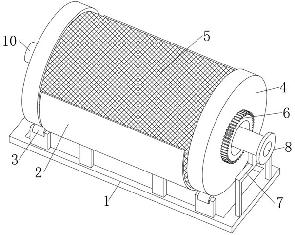
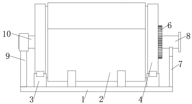
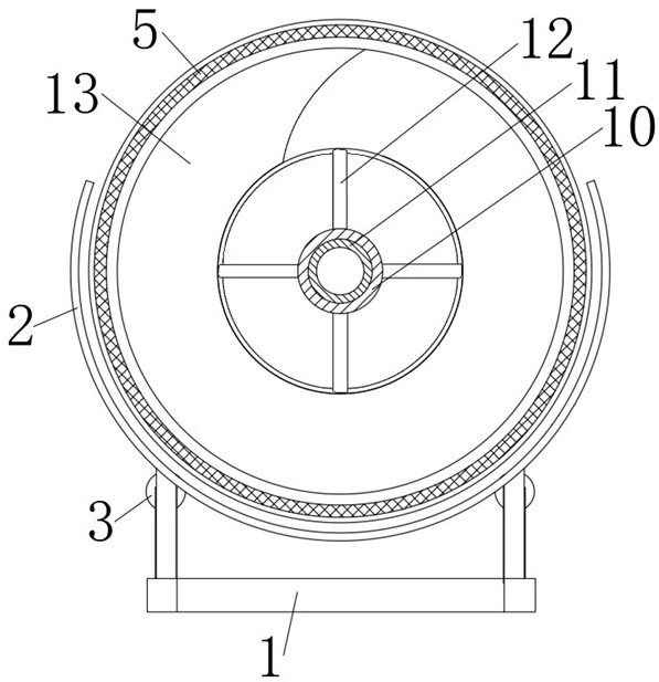
[0027] see Figure 1-8 , a microfilter for wastewater treatment, comprising a base 1, a retaining ring 2 is fixedly connected to the middle of the base 1, support rollers 3 are fixedly connected to both sides of the middle of the base 1, and a sleeve bracket 4 is movably installed above the support roller 3 , the middle part of the sleeve support 4 is fixedly installed with a filter screen 5, the middle part of one side of the sleeve support 4 is fixedly conne...


PUM


Abstract

The invention relates to the technical field of filtering equipment, and discloses a microfilter for waste water treatment and a waste water treatment method thereof. Through the setting of the movable pipe and the circular hole at the outer end of the threaded leaf, when the microfilter is performing filtering work, the outer end of the movable pipe is connected to a negative pressure fan. The impurities inside the filter are sucked out. When the filter rotates for a cycle, the impurities attached to the mesh of the filter can be completely removed to prevent impurities from clogging the mesh of the filter; Forty-five degrees and connected to the water pump. At this time, the water flow will wash the filter screen through the round hole opened on the outer end of the threaded leaf. After the filter screen rotates for one cycle, the water flow sprayed from the round hole will complete the flushing of the entire filter screen. , There will be no dead corners that cannot be cleaned.

Description

technical field [0001] The invention relates to the technical field of filtering equipment, in particular to a microfilter for wastewater treatment and a wastewater treatment method thereof. Background technique [0002] The microfilter is a kind of filter that intercepts fine suspended matter. It has a drum-shaped metal frame. The sleeve bracket can rotate around the horizontal axis. The middle part of the sleeve bracket is equipped with a support net and a working net woven by stainless steel wire, which can be used for The working principle of industrial water filtration, industrial wastewater treatment, etc. is that when the aquaculture water passes through the microporous screen on the sleeve bracket of the microfiltration machine, under the rotation of the sleeve bracket, the solid waste in the aquaculture water is Separation is carried out to purify the water body and achieve the purpose of recycling. [0003] However, the existing microfilters for wastewater treatme...

Claims


Application Information

Patent Timeline
Patent Type & Authority Patents(China)
IPC IPC(8): B01D33/11B01D33/48B01D33/80
CPCB01D33/11B01D33/48B01D33/80
Inventor 王元芳司晓慧
Owner 烟台熙成环保技术有限公司
Why Eureka
Try Eureka