Eureka AIR delivers breakthrough ideas for toughest innovation challenges, trusted by R&D personnel around the world.

Novel motor stator and rotor punching sheet

A stator and rotor punching technology, which is applied in the field of motor stator and rotor punching, can solve the problems of affecting the life of the punch and high punching pressure

Inactive Publication Date: 2020-10-20
惠安县钗新汽车配件中心
View PDF0 Cites 1 Cited by
  • Summary
  • Abstract
  • Description
  • Claims
  • Application Information

AI Technical Summary

Problems solved by technology

[0003] The stamping of the stator and rotor produces a lot of heat during work, and the stamping pressure of the stator and rotor in the prior art is too large during stamping, which affects the life of the punch

Method used


Image

  • Novel motor stator and rotor punching sheet
  • Novel motor stator and rotor punching sheet
  • Novel motor stator and rotor punching sheet

Examples


Embodiment Construction

[0023] The technical solutions in the embodiments of the present invention will be clearly and completely described below in conjunction with the accompanying drawings in the embodiments of the present invention. Obviously, the described embodiments are only some of the embodiments of the present invention, not all of them. Based on the embodiments of the present invention, all other embodiments obtained by persons of ordinary skill in the art without making creative efforts belong to the protection scope of the present invention.

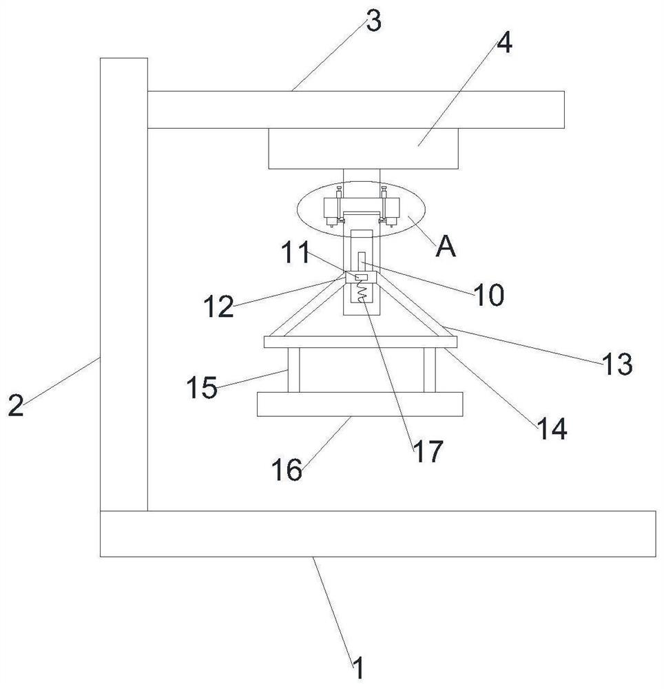
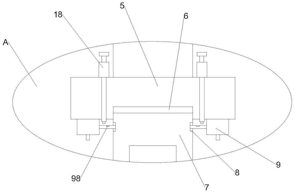
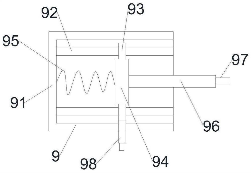
[0024] see Figure 1-4 , in the embodiment of the present invention, a new type of motor stator and rotor stamping includes a bottom plate 1, a vertical column 2 is arranged on the upper part of the bottom plate 1, a top plate 3 is arranged on the top of the vertical column 2, and a cylinder 4 is arranged on the top plate 3 , the free end of the cylinder 4 is connected with a dismounting block 5, and the top of the dismounting block 5 is provided w...


PUM


Abstract

The invention discloses a novel motor stator and rotor punching sheet which comprises a bottom plate, a vertical column is arranged on the upper portion of the bottom plate, a top plate is arranged atthe top end of the vertical column, an air cylinder is arranged on the top plate, the free end of the air cylinder is connected with a dismounting block, and a dismounting groove is formed in the topof the dismounting block and clamped to the top of a positioning column. Mounting grooves are formed in the two sides of the top of the positioning column, and the mounting grooves are matched with adismounting mechanism. The air cylinder is started, the free end of the air cylinder moves downwards, then the disassembling block is driven to move downwards, then the positioning column is driven to move downwards, a punching block is fixed to punch sheets, the punching rod is driven to move upwards, a stabilizing block is arranged in a stabilizing groove in a sliding mode, a spring is driven to be compressed, and the buffering protection effect is achieved.

Description

technical field [0001] The invention relates to the technical field of motor stator and rotor, in particular to a novel motor stator and rotor stamping. Background technique [0002] The motor rotor is the rotating part in the motor. It is a device used to realize the conversion of electrical energy and mechanical energy and mechanical energy and electrical energy. A motor rotor shaft is arranged in the motor rotor, and the motor rotor shaft supports and connects elements such as the rotor, the stator, the motor casing and the end cover of the motor together. Existing electric motors are widely used in agriculture, industry, and tertiary industry services, and are closely related to our lives, but their actual value has not been fully explored and utilized; although the existing solid shaft structure electric motors have many advantages, they are widely used. [0003] The stamping of the stator and rotor produces a lot of heat during work, and the stamping pressure of the ...

Claims


Application Information

Patent Timeline
IPC IPC(8): H02K15/02
CPCH02K15/02
Inventor 赖剑峰张金新
Owner 惠安县钗新汽车配件中心
Why Eureka
Eureka Blog
Learn More