
Transformer area load regulation and control method containing optical storage charging station

A charging station and load technology, which is applied in electric vehicle charging technology, AC network voltage adjustment, energy storage, etc., can solve problems such as long construction period, rigid control method, and unconsidered load control method

Active Publication Date: 2020-10-20
JIANGSU ELECTRIC POWER CO +7
View PDF2 Cites 10 Cited by
  • Summary
  • Abstract
  • Description
  • Claims
  • Application Information

AI Technical Summary

Problems solved by technology

Although in most cases the voltage of the medium-voltage bus can be guaranteed to meet the national standard range, this control method is relatively rigid and does not take into account the actual operating conditions and voltage requirements of the station area. large and long
[0004] On the other hand, a few technologies have considered load control methods including distributed photovoltaic, wind power and electric vehicle access, but among them, photovoltaic power generation is mostly connected to the distribution network as a distributed power source independent of charging stations, and it is mostly discussed from communication devices. Does not fully consider the interests of electric vehicle users, and does not consider the load control method for the integration of photovoltaic, energy storage and charging facilities into the station area of ​​the photovoltaic storage charging station

Method used


Image

  • Transformer area load regulation and control method containing optical storage charging station
  • Transformer area load regulation and control method containing optical storage charging station
  • Transformer area load regulation and control method containing optical storage charging station

Examples


Embodiment 1

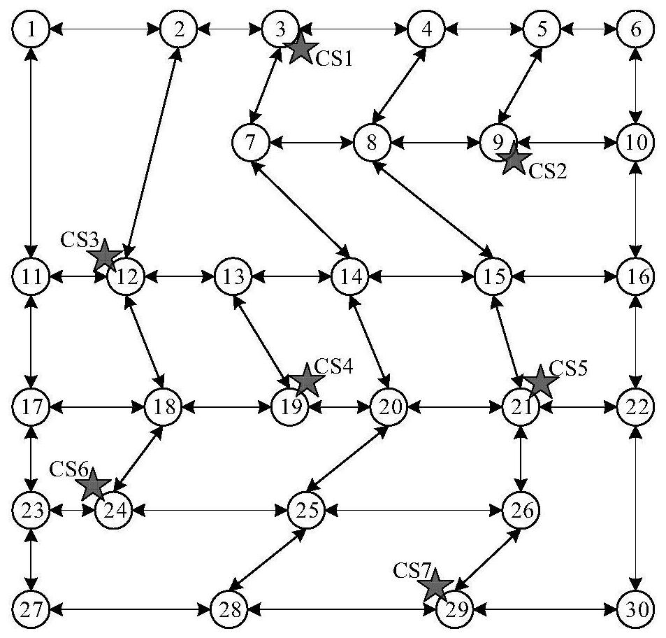
[0178] Such as figure 2 As shown, it represents a 20KMx20KM road network topology map, and 7 solar storage charging stations are set up at locations 3, 9, 12, 19, 21, 24, and 29; the dispatching system uses the Floyd shortest path method to navigate the path for users select. Such as image 3 As shown, the 7 nodes of the distribution network IEEE33 are respectively connected to the optical storage charging station. Assume that there are 800 electric vehicle users in the area who need charging services, and 400 users accept the scheduling strategy. The battery capacity of electric vehicles is Q = 30kWh, Using constant power charging method, the charging rate is 2C, which is common in the market, that is, P c = 60kW. The sub-target weight can be selected according to the actual situation. In this example, λ 1 =λ 2 =λ 3 =1 / 3.

[0179] The multi-objective load regulation of the above-mentioned distribution network with photovoltaic storage charging stations is carried out,...


PUM


Abstract

The invention discloses a transformer area load regulation and control method containing an optical storage charging station, and the method comprises the steps: solving a district load regulation andcontrol multi-target model based on particle swarm optimization, and obtaining the optimal charging starting time of an electric vehicle user and the selected optical storage charging station; and according to the optimal charging starting time of the electric vehicle user and the selected optical storage charging station, guiding the electric vehicle with the charging requirement in the power distribution network to the selected optical storage charging station for charging under the optimal charging starting time. The beneficial effects of the method are that the method carries out the transformer area load regulation and control through combining with the characteristics of a charging load, alleviates the impact caused by the access of the optical storage charging station to a distribution network, and effectively guarantees the transformer area power supply quality; moreover, the method does not need investment of new equipment, and can effectively reduce the load regulation and control cost. 2) the responsivity and satisfaction of the load side are fully considered, the satisfaction is improved while the power demand of the user is ensured, and 3) the economic benefit and theenvironmental benefit are both considered, the load variance can be effectively stabilized, and the carbon emission is reduced.

Description

technical field [0001] The invention relates to a station area load control method for a charging station containing photovoltaic storage, and belongs to the technical field of station area load control. Background technique [0002] At present, with the continuous expansion of the social industrial scale and the higher degree of electrification, the load structure and power consumption law of the station area are becoming more and more complex, while the user side's requirements for power quality are constantly improving. As an environment-friendly means of transportation, electric vehicles have ushered in development opportunities in recent years. At present, the number of electric vehicles in my country has exceeded 3 million. Benefits and economic benefits have been put into operation in many places. However, the disorderly connection of large-scale electric vehicles to the power grid will aggravate the load peak-valley difference, affect the power quality, and bring new...

Claims


Application Information

Patent Timeline
IPC IPC(8): H02J3/32H02J3/14
CPCH02J3/322H02J3/144H02J2203/20Y04S30/12Y04S20/222Y04S30/14Y02B70/3225Y02T90/167
Inventor 潘琪陈广孟屹华陈良亮王瑞升成海生张卫国杨凤坤周静宋杰顾琳琳李化周材邵军军
Owner JIANGSU ELECTRIC POWER CO
Learn More