
Fixing device for capacitor machining

A capacitor processing and fixing device technology, applied in the direction of capacitors, capacitor manufacturing, circuits, etc., can solve the problems of inconvenient operation, processing failure, unsuitable capacitors, etc.

Pending Publication Date: 2020-10-20
长兴立峰电子股份有限公司
View PDF0 Cites 1 Cited by
  • Summary
  • Abstract
  • Description
  • Claims
  • Application Information

AI Technical Summary

Problems solved by technology

[0004] The present invention provides a fixing device for capacitor processing, which aims to solve the above-mentioned problem that manual fixing is not only inconvenient to operate during the welding process of capacitors, but also tends to fail in processing during the operation process. Most of the traditional clamping and fixing devices can only Fixed for a single shape, not applicable for other shapes of capacitors

Method used

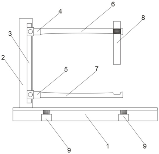
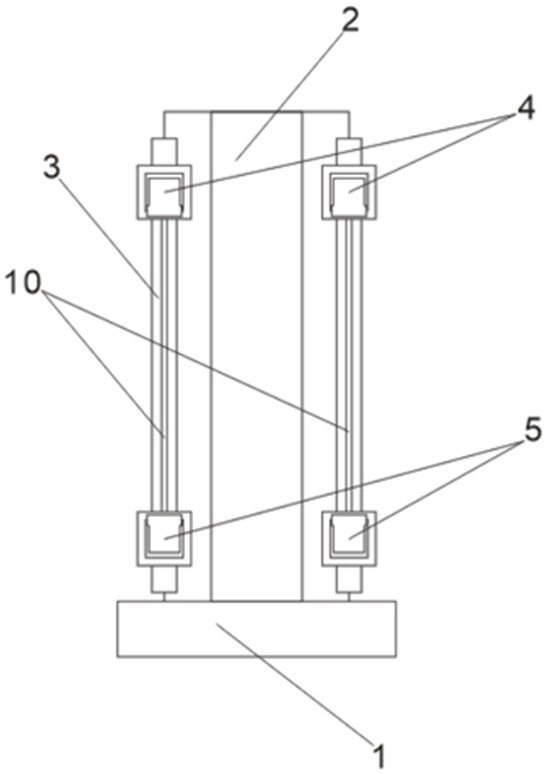
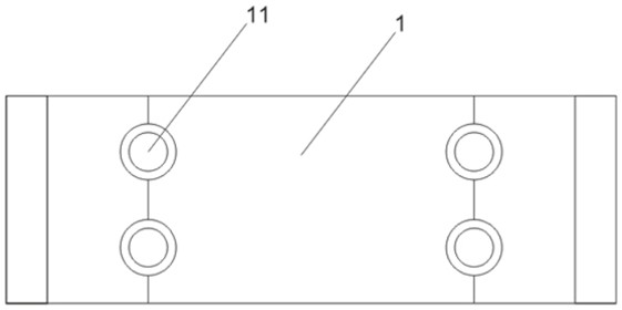

Image

  • Fixing device for capacitor machining
  • Fixing device for capacitor machining
  • Fixing device for capacitor machining

Examples


Embodiment Construction

[0018] In order to make the object, technical solution and advantages of the present invention clearer, the present invention will be further described in detail below in conjunction with the accompanying drawings and embodiments. It should be understood that the specific embodiments described here are only used to explain the present invention, not to limit the present invention.

[0019] In describing the present invention, it should be understood that the terms "length", "width", "upper", "lower", "front", "rear", "left", "right", "vertical", The orientation or positional relationship indicated by "horizontal", "top", "bottom", "inner", "outer", etc. are based on the orientation or positional relationship shown in the drawings, and are only for the convenience of describing the present invention and simplifying the description, rather than Nothing indicating or implying that a referenced device or element must have a particular orientation, be constructed, and operate in a ...


PUM


Abstract

The invention discloses a fixing device for capacitor machining. The device comprises a mounting bottom plate, a limiting plate, a connecting plate, a first sliding groove, a second sliding groove, afirst fixing plate, a second fixing plate, a fixing inserting rod, a compression spring, a sliding rail and a cushion disc; the limiting plate is arranged at the left end of the top of the mounting bottom plate; the limiting plate is provided with the connecting plate; the first sliding groove and the second sliding groove are sequentially formed in the inner side of the sliding rail from top to bottom. The first fixing plate is arranged on the right side of the first sliding groove, the second fixing plate is arranged on the right side of the second sliding groove, the fixing inserting rod isarranged on the right portion of the first fixing plate, the compression spring is arranged in the mounting bottom plate, the sliding rail is arranged on the inner side of the connecting plate, and the cushion disc is arranged at the top of the mounting bottom plate. The fixing device has the advantages of being convenient to adjust and fix different types of capacitors, assisting in stable machining of the capacitors, absorbing sound and reducing noise, and is mainly used for machining and fixing the capacitors.

Description

technical field [0001] The invention belongs to the technical field of capacitor production and processing, and in particular relates to a fixing device for capacitor processing. Background technique [0002] Capacitors, usually referred to as capacitance for their ability to hold charges, are denoted by the letter C. Definition 1: A capacitor, as the name implies, is a 'container for charging', a device that holds charges. English name: capacitor. Capacitors are one of the electronic components widely used in electronic equipment, and are widely used in DC blocking, coupling, bypass, filtering, tuning loops, energy conversion, control, etc. in circuits. Definition: Capacitor, any two conductors (including wires) that are insulated from each other and very close to each other form a capacitor. Capacitors can be divided into fixed capacitors and variable capacitors. [0003] During the welding process of capacitors, manual fixing is not only inconvenient to operate, but al...

Claims


Application Information

Patent Timeline
Patent Type & Authority Applications(China)
IPC IPC(8): H01G13/00
CPCH01G13/00
Inventor 徐建
Owner 长兴立峰电子股份有限公司
Learn More