Composite material compression fixture with coupling effect of load and environment and using method
A composite material and fixture technology, applied in the direction of using stable tension/pressure to test the strength of materials, analyzing materials, instruments, etc., can solve the problem of ineffectiveness, less exploration of service performance tests, electronic instruments and digital displays that cannot work normally, etc. problem, to achieve the effect of simple structure, simple test method and high flexibility
- Summary
- Abstract
- Description
- Claims
- Application Information
AI Technical Summary
Problems solved by technology
Method used
Image


Examples
Embodiment 1
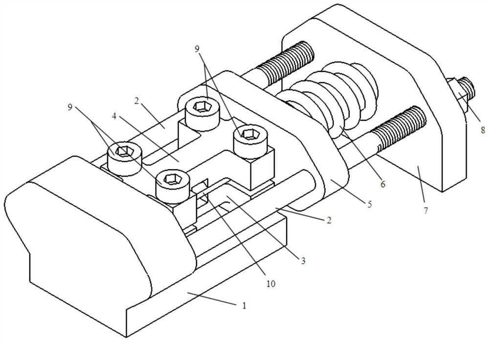
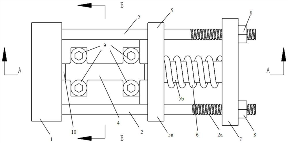
[0031] Such as Figure 1-5 As shown, this embodiment provides a composite material compression fixture that couples the load and the environment, including a fixture base 1, a holder, a spring frame 5, a long screw 2, a spring 6, a retainer 7 and a limit nut 8; The holder is used to clamp the composite material sample 10; one end of the long screw 2 is connected to the clamp base 1, the other end of the long screw 2 is provided with threads, and the stopper 7 is arranged on the long screw The other end of 2, the limit nut 8 is connected with the thread; the spring frame 5 is a T-shaped structure, and a guide hole is arranged in the middle of the blocking plate 7, and the two ends of the spring frame 5 are movably sleeved On the long screw rod 2, the spring 6 is sheathed on the tail end of the spring frame 5, and the tail end of the spring frame 5 extends into the guide hole.
[0032] The fixture base 1 is composed of a stopper 1a and a mounting platform 1b. In order to ensure...
Embodiment 2
[0042] This embodiment provides a method for using a composite material compression fixture coupled with load and environment, including the following steps:
[0043] The composite material sample 10 is a composite material plate reinforced with carbon fiber, glass fiber, aramid fiber, basalt fiber, sulfonamide fiber, and ultra-high molecular weight polyethylene fiber, and the thickness of the plate is 0.5mm-2mm, preferably 1mm; The length of the composite material sample 10 is 75mm-150mm, preferably 80mm, and the width of the composite material sample 10 is 5mm-30mm, preferably 15mm. The number of composite material samples 10 in the same batch is 10 or more.
[0044] Further, 5 composite material samples 10 of the same batch are randomly selected for uniaxial compression performance testing, and the 5 composite material samples 10 are compressed to fracture to calculate the ultimate compressive strength of the composite material sample 10 .
[0045] After assembling the pa...
Embodiment 3
[0064] This embodiment relates to a test method for a composite material compression fixture utilizing the coupling effect of load and environment, which specifically includes the following steps:
[0065] Composite material sample 10 with aramid fiber twill fabric as reinforcement, sample 10 has a length of 80 mm, a width of 15 mm, and a thickness of 1 mm. Utilize the compression fixture to clamp the composite material sample 10, and apply compression to the spring 6, so that the load strength applied by the spring 6 to the composite material sample 10 is 40% of the ultimate compressive load of the composite material, and place the adjusted compression fixture horizontally In the salt spray test chamber, the salt spray solution is 5% sodium chloride solution and glacial acetic acid is added dropwise to reduce the pH value of the solution to between 3.1 and 3.3, and the sedimentation rate of the salt spray is 1 to 2ml / 80cm 2Between h. The test temperature is 35°C. The test d...
PUM
| Property | Measurement | Unit |
|---|---|---|
| depth | aaaaa | aaaaa |
| length | aaaaa | aaaaa |
| length | aaaaa | aaaaa |
Abstract
Description
Claims
Application Information
 - R&D
- Intellectual Property
- Life Sciences
- Materials
- Tech Scout
- Unparalleled Data Quality
- Higher Quality Content
- 60% Fewer Hallucinations
Browse by: Latest US Patents, China's latest patents, Technical Efficacy Thesaurus, Application Domain, Technology Topic, Popular Technical Reports.
© 2025 PatSnap. All rights reserved.Legal|Privacy policy|Modern Slavery Act Transparency Statement|Sitemap|About US| Contact US: help@patsnap.com