
Construction site fence connecting beam bottom fixing device

A bottom-fixed, construction site technology, applied in the direction of fences, buildings, building types, etc., can solve problems such as the impact of fences

Inactive Publication Date: 2020-10-20
胡永强
View PDF1 Cites 0 Cited by
  • Summary
  • Abstract
  • Description
  • Claims
  • Application Information

AI Technical Summary

Problems solved by technology

However, when the fence is in use, the poles are generally directly inserted into the ground, but most of the fences do not take the columns or beams between the fences as the key focus. For simple insertion of the columns into the ground, Whether it is possible to ensure the stability of the column and not tilt or collapse in the case of wind blowing and shaking, this fence also has such problems. Once the connecting column or beam tilts, it will have a great impact on the entire fence, so it needs to be designed A device capable of stably fixing connecting columns or connecting beams between fences

Method used


Image

  • Construction site fence connecting beam bottom fixing device
  • Construction site fence connecting beam bottom fixing device
  • Construction site fence connecting beam bottom fixing device

Examples


Embodiment 1

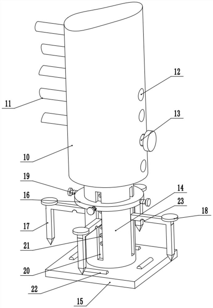
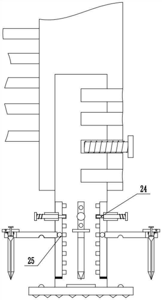
[0021] see Figure 1-3 , a construction site fence connecting beam bottom fixing device, comprising a connecting beam 10, a fence rod 11, a fixing rod 14; the fence rod 11 is fixedly installed on one side of the connecting beam 10, and the inner bottom of the connecting beam 10 is set as a cavity structure and A vertical fixing rod 14 is telescopically connected. The lower part of the right side wall of the connecting beam 10 is provided with a plurality of sets of limit holes 12 side by side. The interior of the limit holes 12 extends into the fixed rod 14. The limit holes 12 The limit pin 13 is connected with the middle plug-in type, and the height difference between the fixing rod 14 and the inner bottom of the limit hole 12 is adjusted, and then the limit pin 13 is used to limit and fix. The bottom of the fixing rod 14 is fixedly installed with a bottom plate 15 in a rectangular structure, and the bottom of the bottom plate 15 is fixedly mounted with evenly arranged cones ...

Embodiment 2

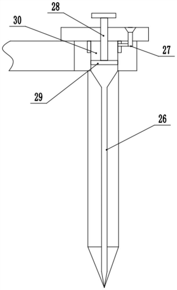
[0024] On the basis of the first embodiment, a water injection pipe 26 whose bottom end extends to the bottom cone of the insertion rod 17 is provided inside the vertical section of the insertion rod 17 , and a piston with a diameter larger than that of the water injection pipe 26 is connected to the top of the water injection pipe 26 . Rod 30, the interior of the piston rod 30 is slidably connected with a piston plate 29, the upper center of the piston plate 29 is fixedly installed with a piston rod 28 extending upward to the outer top of the hammer plate 18, and a pressure plate is fixedly installed on the top of the piston rod 28, By moving the piston plate 29 up and down, the water inside the water injection pipe 26 is squeezed and pressed into the soil to be inserted at the bottom of the plunger 17, thereby reducing the resistance of the plunger 17 when it moves downward. The top right side of the piston rod 30 is connected with a water delivery pipe 27 whose end extends t...


PUM


Abstract

The invention relates to construction safety appliances, and discloses a construction site fence connecting beam bottom fixing device. The construction site fence connecting beam bottom fixing deviceincludes a connecting beam, fence poles, and a fixing pole; the inner bottom of the connecting beam is arranged to be a cavity structure and is telescopically connected with a vertical fixing rod; four sets of vertical sliding grooves are equally spaced on the outer side of the middle and lower parts of the fixing rod; the inside of the sliding grooves are slidingly connected with balls; the outside of the balls is connected with an inserting rod with an L-shaped structure with the end facing down in a rolling manner; the straight section of the inserting rod crosses a bottom plate; the insideof the sliding groove is provided with plurality sets of limit grooves at equal intervals from top to bottom; a set of clamping plate is slidingly sleeved on the fixing rod on the upper side of the inserting rod; the position of the clamping plate corresponding to the sliding groove is telescopically connected with a spring rod; the outer end of the spring rod is fixedly installed with a limit plate; and a spring is sleeved on the spring rod located between the limit plate and the outside of the clamping plate. The construction site fence connecting beam bottom fixing device has the advantages of simple operation, adjustable height, high fixability, and is beneficial to popularization and use.

Description

technical field [0001] The invention relates to a construction safety appliance, in particular to a bottom fixing device of a construction site fence connecting beam. Background technique [0002] During the construction process, it is often necessary to set up safety fences to remind construction workers or passersby to pay attention to construction safety. The safety fences currently used are generally fixed on the ground with a certain number of columns, and some ropes are pulled or tied between the columns. , in order to play the role of prompting and intercepting workers or pedestrians. [0003] Chinese Patent (Announcement No.: CN 203160825 U, Announcement Date: 2013.08.28) discloses a connection and combined safety fence for construction sites, comprising a plurality of vertical poles, and the bottom ends of the vertical poles are respectively connected with vertical pole fixing devices. A horizontal rail is connected between two adjacent vertical poles, and connecti...

Claims


Application Information

Patent Timeline
Patent Type & Authority Applications(China)
IPC IPC(8): E04H17/20E04H17/22
CPCE04H17/20E04H17/22
Inventor 胡永强
Owner 胡永强
Learn More