
Cement slurry preparing, stirring and conveying integrated system

An integrated system and cement slurry technology, which is applied in the direction of cement mixing device, clay preparation device, mixing operation control, etc., can solve the problems of pulping quality influence, installation, disassembly and maintenance time-consuming and laborious, low precision, etc.

Pending Publication Date: 2020-10-20
三川德青工程机械有限公司
View PDF3 Cites 1 Cited by
  • Summary
  • Abstract
  • Description
  • Claims
  • Application Information

AI Technical Summary

Problems solved by technology

However, the installation, disassembly and maintenance of the system are time-consuming and labor-intensive
Moreover, the pulping equipment is generally operated manually or semi-automatically. A cement pulping station needs about 4 to 5 people per shift. The labor intensity is high, the output is not high, the pulping precision is not accurate, and the pulping quality is also affected.
[0003] Chinese patent document CN 207260139 U records a kind of intelligent pulping equipment for cement mixing pile machine, by setting a weighing device at the cement discharge port, and setting a flow rate detector on the water pipe, thereby automatically controlling the ratio of cement and water, However, the accuracy of this measurement method is low, and the configuration quality of cement slurry is difficult to guarantee
Chinese patent document CN 208263155 U records a kind of integrated horizontal cement slurry system, which integrates the slurry storage tank, water tank and mixer together to make slurry together, but the degree of automation of this scheme is relatively low
Difficult to realize automatic mixing

Method used


Image

  • Cement slurry preparing, stirring and conveying integrated system
  • Cement slurry preparing, stirring and conveying integrated system
  • Cement slurry preparing, stirring and conveying integrated system

Examples


Embodiment 1

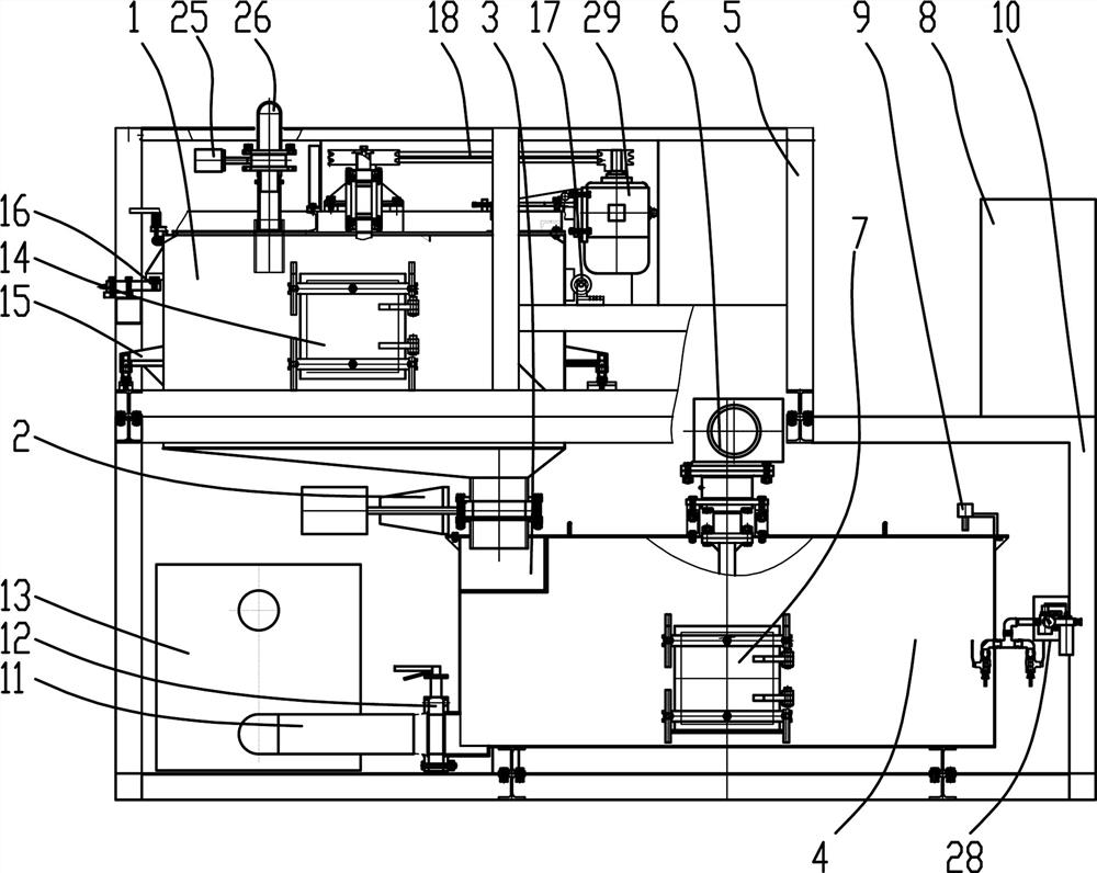
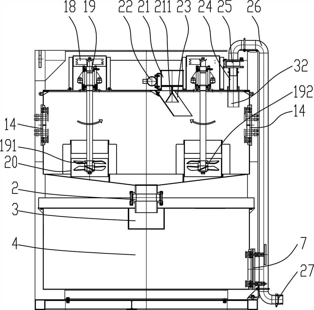
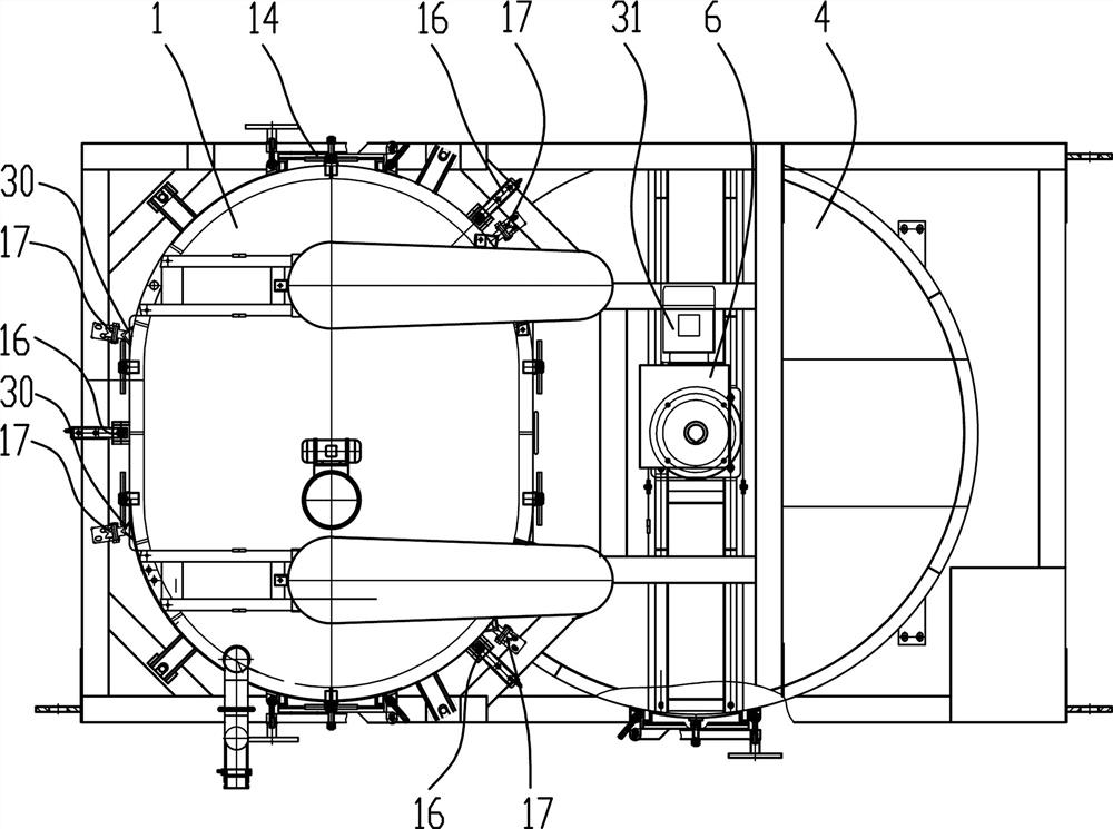
[0029] Such as Figure 1~3 Among them, an integrated system for mixing and transporting cement slurry, including a pulper 1 and a mixer 4, the pulper 1 is located above the mixer 4, and the slurry outlet pipeline 11 of the mixer 4 is connected to the inlet of the delivery pump 13; preferably , A manual valve 12 or an electronically controlled valve is also provided in the slurry outlet pipeline 11.

[0030] The pulping machine 1 is supported on the upper frame 5 by a plurality of load cells 16, and the top of the pulping machine 1 is provided with a water inlet pipeline 26. The water inlet pipeline 26 is provided with an automatic water inlet valve 25, and the water inlet pipeline 26 is connected to the The liquid inlet 32 ​​at the top of the cylinder of the pulping machine 1 is flexibly connected;

[0031] A cement feed port 21 is also provided on the top of the pulp machine 1 . With this structure, the automatic preparation of cement slurry is realized, and the cement and ...


PUM


Abstract

The invention provides a cement slurry preparing, stirring and conveying integrated system. The cement slurry preparing, stirring and conveying integrated system comprises a slurry preparing machine and a stirring machine; the slurry preparing machine is located above the stirring machine, and a slurry outlet pipeline of the stirring machine is connected with an inlet of a conveying pump; the slurry preparing machine is supported on an upper frame through a plurality of weighing sensors, a water inlet pipeline is arranged at the top of the slurry preparing machine, an automatic water inlet valve is arranged on the water inlet pipeline, and the water inlet pipeline is movably connected with a liquid inlet in the top of a barrel body of the slurry preparing machine; and a cement feeding holeis further formed in the top of the slurry preparing machine. According to the cement slurry preparing, stirring and conveying integrated system, the slurry preparing machine is stacked above the stirring machine by adopting the modularized frame stacking structure, and the fed cement and water can be accurately weighed, so that the accuracy of the water cement ratio is ensured. The system is convenient to mount and dismount on site, high in slurry preparing precision, high in speed and small in number of operators, and only one operator is needed at least.

Description

technical field [0001] The invention relates to the field of cement slurry preparation, in particular to an integrated system for mixing and transporting cement slurry. Background technique [0002] Existing large-scale structures, such as the site of a hydropower station construction pulping station, are usually equipped with cement silos and screw conveyors, centralized water supply systems, air compressors, and then equipped with independent pulping machines, mixers and slurry pumps, and Set up corresponding pipelines to form a pulping system. But the installation, disassembly and maintenance of this system are all time-consuming and laborious. Moreover, the pulping equipment is generally operated manually or semi-automatically. A cement pulping station needs about 4 to 5 people per shift. The labor intensity is high, the output is not high, the pulping precision is not accurate, and the pulping quality is also affected. [0003] Chinese patent document CN 207260139 U r...

Claims


Application Information

Patent Timeline
IPC IPC(8): B28C5/16B28C7/04B28C7/06B28C7/12
CPCB28C5/16B28C7/0404B28C7/06B28C7/12
Inventor 朱科甘虎肖桂华
Owner 三川德青工程机械有限公司
Learn More