
Groove pressing structure of plate bending machine

A bending machine and grooving technology, which is applied in the field of grooving structure of a plate bending machine, can solve the problems of low processing accuracy, poor dimensional and quality of grooving, etc.

Inactive Publication Date: 2020-10-20
津阳创展(天津)金属科技有限公司
View PDF0 Cites 0 Cited by
  • Summary
  • Abstract
  • Description
  • Claims
  • Application Information

AI Technical Summary

Problems solved by technology

[0002] The plate bending machine is about to bend the flat plate to form a folded plate. At present, the dynamic pressure head and the fixed pressure head of a specific shape can directly bend the groove shape in the flat plate. stress, it will lead to poor dimensional and groove quality of the indentation
[0003] Therefore, at present, the form of multiple bending into grooves is still mostly used. However, the disadvantage of multiple bending into grooves is that it is difficult to avoid the dimensional deviation of the previous process. Taking rectangular grooves or open grooves as an example, four times of bending are required. The process errors after four bendings are superimposed, resulting in low processing accuracy

Method used


Image

  • Groove pressing structure of plate bending machine
  • Groove pressing structure of plate bending machine

Examples


Embodiment Construction

[0022] Below, the present invention is described in detail with reference to accompanying drawing and embodiment:

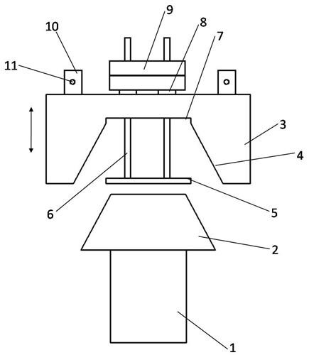
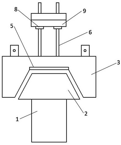
[0023] Such as Figure 1~2 As shown, a pressure groove structure of a plate bending machine includes a constant pressure table 1 on the workbench of the plate bender and a dynamic pressure head 3 moving toward or away from the constant pressure table 1. The upper end of the constant pressure table 1 is provided with a fixed Indenter 2, in the dynamic indenter 3 is formed a matching groove 4 that matches the fixed indenter 2, and four through holes are formed in the bottom of the indenter 4, and a slidable connecting rod is arranged in the through holes 6. The lower end of the connecting rod 6 is connected to the vertical pressure plate 5, and the upper part of the connecting rod 6 forms a collar 8, and the collar 8 limits the connecting rod 6 axially.

[0024] The constant pressure head 2 is strip-shaped, and the cross section of the constant pressure head 2 is ...


PUM


Abstract

The invention discloses a pressing groove structure of a plate bending machine, comprising a fixed pressing table and a movable pressing head, wherein the fixed pressing table is arranged on a workbench of the plate bending machine, and the movable pressing head moves towards or away from the fixed pressing table. A fixed pressing head is arranged at the upper end of the fixed pressing table, a matching groove matched with the fixed pressing head is formed in the movable pressing head, four through holes are formed in the groove bottom of the matching groove, slidable connecting rods are arranged in the through holes, the lower ends of the connecting rods are connected with a vertical pressing plate, shaft rings are formed on the upper portions of the connecting rods, and the shaft rings axially limit the connecting rods. According to the invention, the movable pressing head is connected with a cylinder rod of a hydraulic cylinder through a connector; the movable pressing head is driven by the cylinder rod to move towards the fixed pressing head, the matching groove in the movable pressing head is matched with the fixed pressing head to achieve groove pressing, in the process, thevertical pressing plate is always matched with the fixed pressing head to press the groove bottom of a formed groove of a plate, the pressure applied by the vertical pressing plate is the sum of the gravity of a balance weight plate, the connecting rods and the vertical pressing plate, and groove pressing efficiency is high, and the quality is good.

Description

technical field [0001] The invention belongs to the field of groove structure of plates, and in particular relates to a groove structure of a plate bending machine. Background technique [0002] The plate bending machine is about to bend the flat plate to form a folded plate. At present, the dynamic pressure head and the fixed pressure head of a specific shape can directly bend the groove shape in the flat plate. If the stress is too high, it will lead to poor dimensionality and quality of the groove. [0003] Therefore, at present, the form of multiple bending into grooves is still mostly used. However, the disadvantage of multiple bending into grooves is that it is difficult to avoid the dimensional deviation of the previous process. Taking rectangular grooves or open grooves as an example, four times of bending are required. The process errors after four bendings are superimposed, resulting in low processing accuracy. Contents of the invention [0004] The present inv...

Claims


Application Information

Patent Timeline
Patent Type & Authority Applications(China)
IPC IPC(8): B21D5/00
CPCB21D5/00
Inventor 许继华
Owner 津阳创展(天津)金属科技有限公司
Learn More