Cleaning device for solar photovoltaic panel and cleaning method of solar photovoltaic panel

A technology for a solar photovoltaic panel and a cleaning device, which is applied in the field of solar power generation, can solve the problems of damage to the solar photovoltaic panel, poor cleaning effect, and laborious device driving.

Active Publication Date: 2020-10-20
徐州顺泰新能源发电有限公司
View PDF5 Cites 4 Cited by
  • Summary
  • Abstract
  • Description
  • Claims
  • Application Information

AI Technical Summary

Problems solved by technology

[0004] The technical problem to be solved by the present invention is that the cleaning device used for solar photovoltaic panels in the prior art cannot throw snow away from the solar photovoltaic panel, resulting in the accumulation of snow in front of the cleaning device during the cleaning process, causing the device to be pushed hard and unable to last Cleaning at a distance leads to poor cleaning effect. At the same time, the snow plowing component is directly in contact with the solar photovoltaic panel, which is easy to scratch the surface of the solar photovoltaic panel and cause damage to the solar photovoltaic panel.

Method used


Image

  • Cleaning device for solar photovoltaic panel and cleaning method of solar photovoltaic panel
  • Cleaning device for solar photovoltaic panel and cleaning method of solar photovoltaic panel
  • Cleaning device for solar photovoltaic panel and cleaning method of solar photovoltaic panel

Examples


Embodiment 1

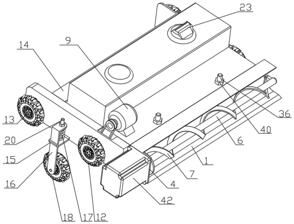
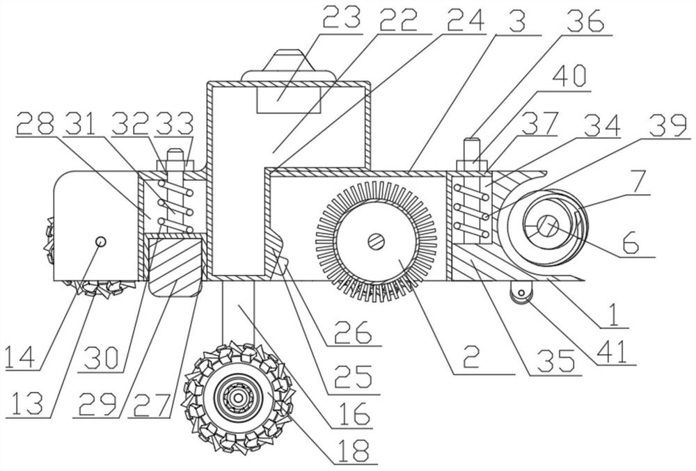
[0042] Such as Figure 1-7 As shown, a cleaning device for solar photovoltaic panels includes a shovel plate 1, a cleaning roller 2, a housing 3, a snow guide assembly, a walking device, a transmission assembly and a power device, and the housing 3 is a box with an open bottom One end of the housing 3 is provided with a guide groove 34, one end of the shovel plate 1 is in an arc-shaped structure, and the other end is provided with a slider 35 that cooperates with the guide groove 34, and the top of the slider 35 A second connecting rod 36 is provided, a top plate 37 is provided on the top of the guide groove 34, a fourth through hole 38 is arranged on the top plate 37, and the end of the second connecting rod 36 passes through the fourth through hole 38 The shovel plate 1 is installed in the guide groove 34, and the shovel plate 1 can move along the axis direction of the guide groove 34, the second connecting rod 36 is sleeved with a third spring 39, and the third spring 39 T...

Embodiment 2

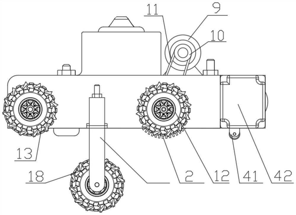
[0044] Such as Figure 1-7 As shown, this embodiment is basically the same as Embodiment 1, the difference is that the snow guide assembly includes a rotating shaft 6 and a guide vane 7, the guide vane 7 has a spiral structure, and the two ends of the guide vane 7 are respectively fixed On the rotating shaft 6 , the end of the rotating shaft 6 passes through the first through hole 5 to place the snow guide assembly in the blade 1 , and the rotating shaft 6 can rotate along its own axis. Also include guard plate 8, described power unit comprises first motor 9 and second motor 42, and described transmission assembly comprises belt pulley 10 and transmission belt 11, and one end of described cleaning roller 2, on the output shaft of first motor 9 all A pulley 10 is provided, the transmission belt 11 is wound on the pulley 10, the rotation of the first motor 9 can drive the rotation of the cleaning roller 2, and the second motor 42 is arranged on the end plate 4, so The output sh...

Embodiment 3

[0046] Such as Figure 1-7As shown, this embodiment is basically the same as Embodiment 2, the difference is that it also includes a water spray assembly, the water spray assembly includes a water storage tank 22, an air pressurization assembly 23, and the top of the housing 3 is provided with Installation port 24, the water storage tank 22 is installed in the installation port 24, and the water storage tank 22 is located at the rear of the cleaning roller 2, and the side wall of the water storage tank 22 near the cleaning roller 2 side is provided with a mounting Platform 25, the cross-section of the installation platform 25 is a triangular structure, the installation platform 25 is provided with a number of high-pressure atomization nozzles 26, and the spraying direction of the high-pressure atomization nozzles 26 is towards the lowest end of the cleaning roller 2, and the air pressure The component 23 is installed on the water storage tank 22 to pressurize the inside of the...


PUM


Abstract

The invention discloses a cleaning device for a solar photovoltaic panel and a cleaning method of the solar photovoltaic panel. A housing is of a box-like structure with a bottom opening, one end of the housing is provided with a guide groove, one end of a shovel plate is of an arc-shaped structure, the other end of the shovel plate is provided with a sliding block, a second connecting rod is arranged at the top of the sliding block, the top of the guide groove is provided with a top plate, the top plate is provided with a fourth through hole, the end portion of the second connecting rod passes through the fourth through-hole to mount the shovel plate in the guide groove, the shovel plate can move in the axial direction of the guide groove, the second connecting rod is sleeved with a thirdspring, the third spring is located between the sliding block and the top plate, a second limiting block is arranged at one end, away from the sliding block, of the second connecting rod, a bottom plate of the shovel plate is provided with a supporting walking wheel, a cleaning roller is installed in the shell, the end face of one side of the shovel plate is provided with an end plate, the end plate is provided with a first through hole, one end of a snow guiding assembly penetrates through the first through hole to arrange the snow guiding assembly in the shovel plate, a walking device is mounted on the two sides of the housing, and a power device can drive the cleaning roller and the snow guiding assembly to rotate.

Description

technical field [0001] The invention relates to the technical field of solar power generation, in particular to a cleaning device and a cleaning method for solar photovoltaic panels. Background technique [0002] Solar photovoltaic panels are often installed in the field environment, and the field environment often has sandstorm weather and snowy weather. As the solar photovoltaic panel is used for a long time, impurities such as dust and snow will gradually deposit on the surface of the solar photovoltaic panel, which will affect the absorption of solar energy by the solar photovoltaic panel, thereby affecting the power generation efficiency of the equipment, and will easily cause damage to the solar photovoltaic panel. Fault. [0003] One of the existing cleaning devices for solar photovoltaic panels uses a motor to drive the cleaning roller to rotate to clean dust and snow. However, during the cleaning process, the cleaning roller cannot throw dust and snow away from the...

Claims


Application Information

Patent Timeline
IPC IPC(8): B08B1/00B08B1/04B08B3/02B08B13/00H02S40/12H02S40/10
CPCB08B3/02B08B13/00H02S40/12H02S40/10B08B1/12B08B1/165B08B1/32Y02E10/50
Inventor 李凤英
Owner 徐州顺泰新能源发电有限公司
Why Eureka
Try Eureka