
Tractor rear suspension

a rear suspension and tractor technology, applied in the field of suspensions, can solve the problems of no major manufacturer of tractors selling commercially accepted agricultural tractor rear suspensions with sprung rear suspensions, rear suspension to squat, and operator squatting can be disconcerting, and achieve the effect of a smoke-free rid

Active Publication Date: 2007-04-17
BLUE LEAF I P INC
View PDF17 Cites 6 Cited by
  • Summary
  • Abstract
  • Description
  • Claims
  • Application Information

AI Technical Summary

Benefits of technology

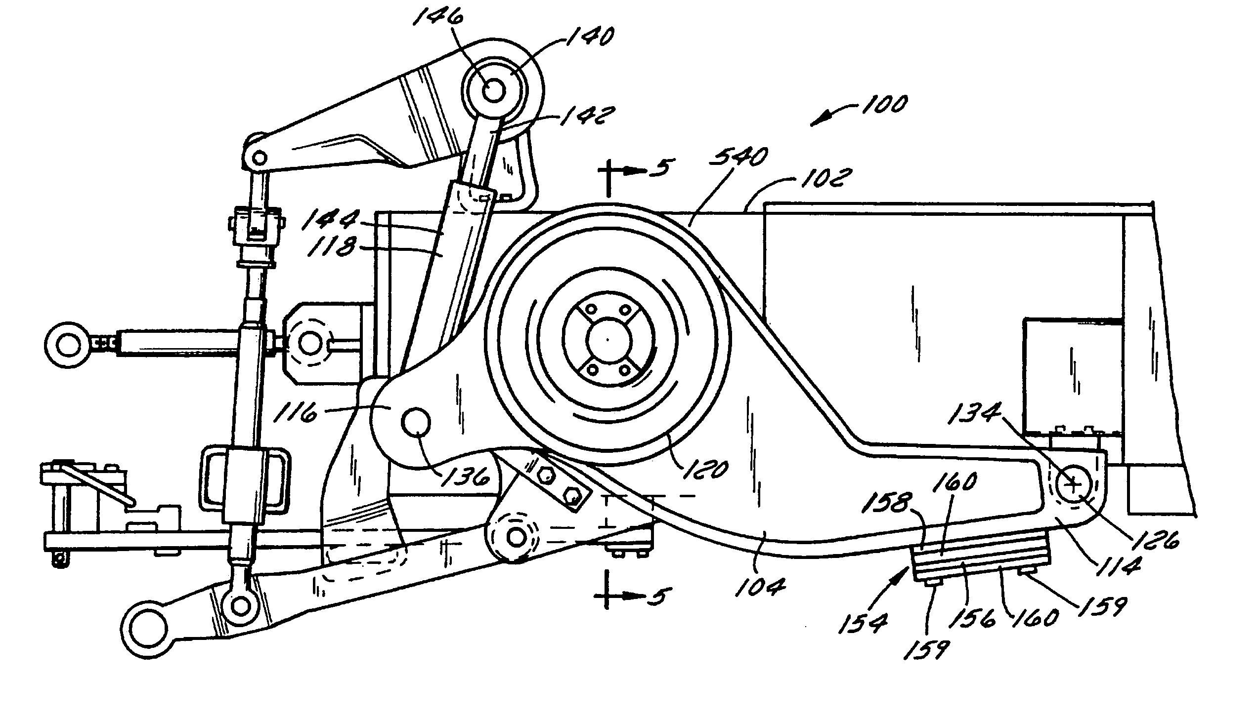
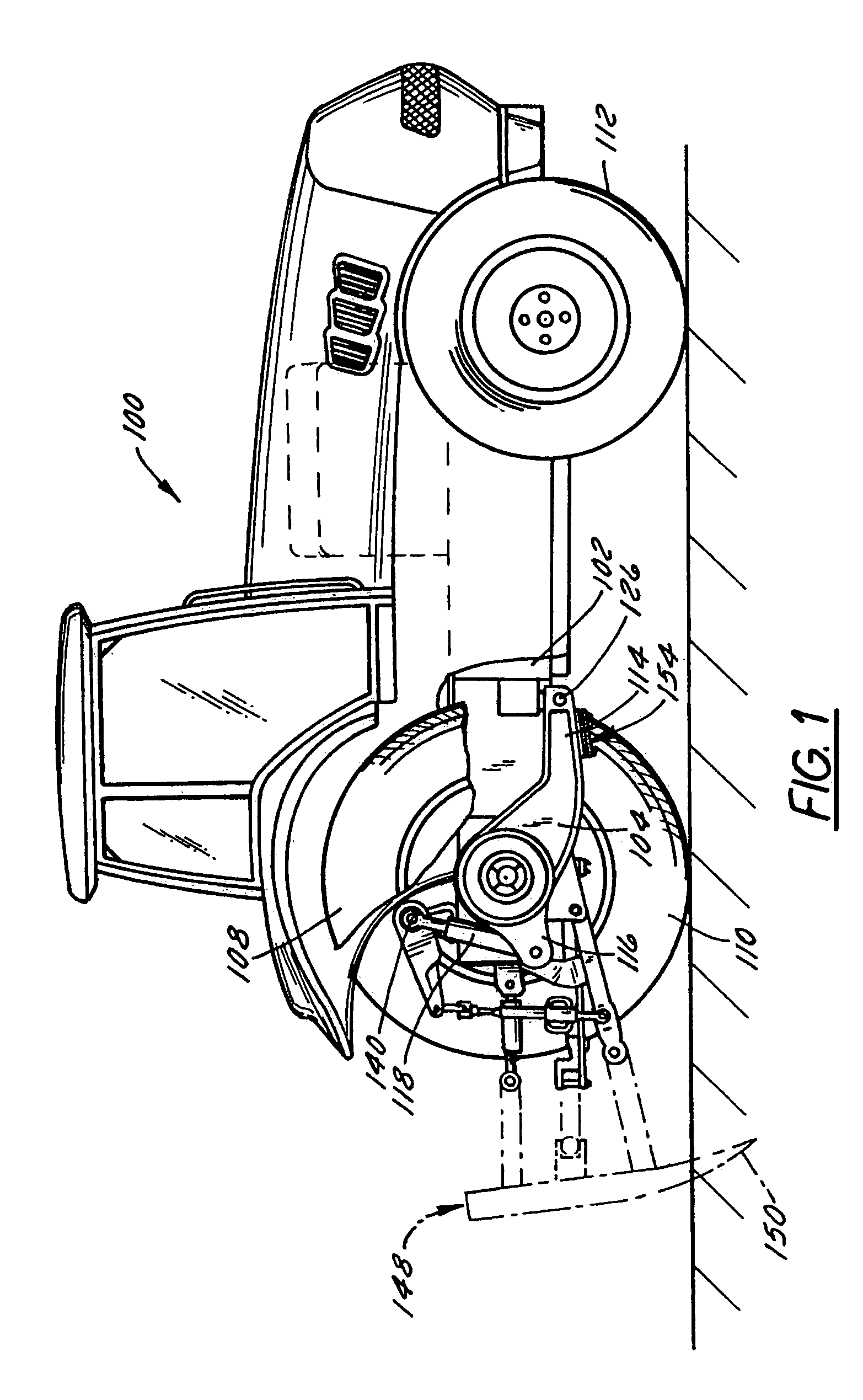
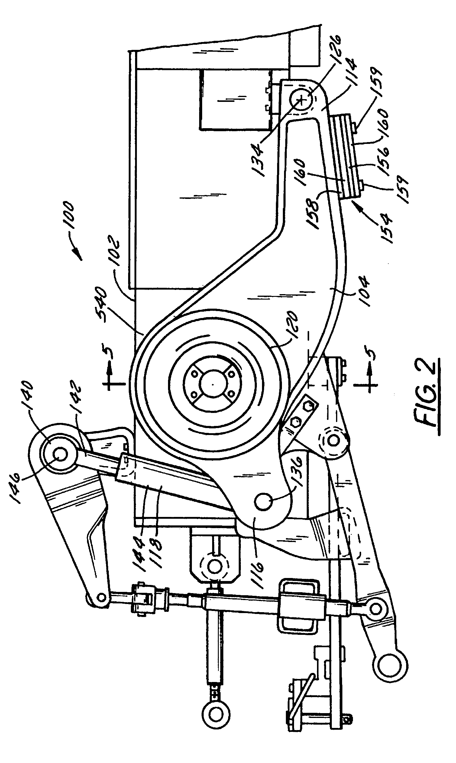
The patent describes a tractor with a sprung rear suspension system that includes a pair of suspension arms and a planetary gear system. The suspension arms support a rear wheel and the planetary gear system generates reaction torque that counteracts the weight transfer to the rear wheels. This results in a smoother ride for the operator and better control of the implement depth. The rear suspension system also allows for a smoother ride and accurate control of the implement depth when the tractor is loaded by a horizontal load. The patent also describes a tractor with two such suspension systems on the left and right rear of the tractor.

Problems solved by technology

As of today, however, no major manufacturer of tractors sells a commercially accepted agricultural tractor with a sprung rear suspension.
If the rear wheels were suspended on the frame rather than being fixed, the moment MP will not at first lift the front wheels, but it will tend to cause the rear suspension to squat.
Such squatting can be disconcerting to the operator and can also wreak havoc on implement depth-control systems, which typically require a constant relationship between the tractor-frame and implement-frame heights.

Method used


Image

  • Tractor rear suspension
  • Tractor rear suspension
  • Tractor rear suspension

Examples


Embodiment Construction

[0032]While the present invention is susceptible of being made in any of several different forms, the drawings show a particularly preferred form of the invention. One should understand, however, that this is just one of many ways the invention can be made. Nor should any particular feature of the illustrated embodiment be considered a part of the invention, unless that feature is explicitly mentioned in the claims. In the drawings, like reference numerals refer to like parts throughout the several views.

[0033]The tractor rear suspension according to the preferred embodiments is constructed in such a way that increases in implement forces (which may occur when, for example, a plow or ripper implement being drawn by a tractor comes across a buried object such as a rock or root) are at least partially compensated for by the rear suspension and the final-drive transmission. In other words, the rear suspension according to the preferred embodiments is effectively instantaneously stiffen...


PUM


Abstract

A tractor has sprung left and right rear suspensions, each suspension including a suspension arm pivotally coupled to the tractor chassis to pivot about a pivot point. A planetary gear system is fixed to the suspension arm having a sun gear driven by the engine and a planetary gear carrier that is coupled to and drives an axle supporting a rear wheel. The ring gear is fixed with respect to the suspension arm.

Description

FIELD OF THE INVENTION[0001]The present invention relates generally to suspensions. More particularly, it relates to tractor suspensions, and even more particularly to rear suspensions for agricultural tractors.BACKGROUND OF THE INVENTION[0002]Agricultural tractors have traditionally been unsprung. From their earliest beginnings in the late 1800's they have been supported on fixed axles extending from the chassis.[0003]Originally tractors were used as stationary engines. Located in a fixed position in a field, farmers would gather crops to be threshed and bring them in wagon loads to the tractor and a belt-driven threshing machine. In these early days the ability to move fast was not important.[0004]Tractors were gradually modified to tow implements such as plows, rakes, harrows, planters, and manure spreaders through agricultural fields. These mobile tractors did not need a great deal of speed since they replaced horses or oxen and needed only enough power to tow implements at hors...

Claims


Application Information

Patent Timeline
Patent Type & Authority Patents(United States)
IPC IPC(8): B60K17/04
CPCB60G3/12B60G3/145B60K17/046B60K17/165B60K17/22B60G2200/22B60G2202/154B60G2204/419B60G2300/082
Inventor BORDINI, GIORGIO
Owner BLUE LEAF I P INC
Learn More