Air supply control method and device and air conditioning equipment
A control method and air conditioning technology, which are applied in the fields of air supply control methods, air conditioning equipment, and devices, can solve the problem of inability to measure the length of the air outlet duct, and achieve the effect of improving comfort.
- Summary
- Abstract
- Description
- Claims
- Application Information
AI Technical Summary
Problems solved by technology
Method used
Image
Examples
Embodiment 1
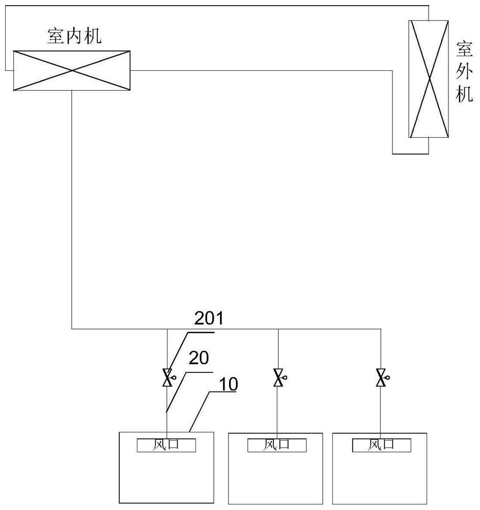
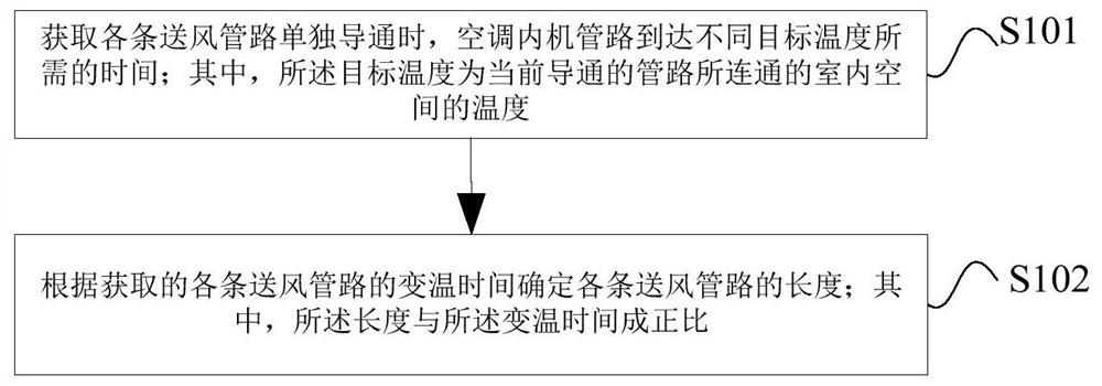
[0046] This embodiment provides an air supply control method, which is applied to an air conditioner, figure 1 For applying the structural representation of the air conditioner of the present invention, as figure 1 As shown, the air conditioner includes an indoor unit and an outdoor unit. The inner unit of the air conditioner communicates with a plurality of indoor spaces 10 through air supply pipelines 20 of different lengths and air outlets. The air supply pipeline 20 is provided with a valve 201 for controlling air volume, figure 2 It is a flow chart of the air supply control method according to an embodiment of the present invention, such as figure 2 As shown, the method includes:
[0047] S101. Obtain the temperature change time required for the pipelines of the air conditioner internal unit to reach the target temperature when each air supply pipeline is turned on separately; The target temperature is different each time the temperature change time is detected.
[...
Embodiment 2
[0053] This embodiment provides another air supply control method. Before determining the length of the pipeline according to the temperature variation time, the temperature variation time must be obtained first. In order to sequentially obtain the temperature variation time of each air supply pipeline, step S101 includes: controlling the operation of the air conditioner Turn off after a preset time, so that the air conditioner indoor unit pipeline and each indoor space will have a temperature difference; When the temperature reaches a certain value, after the second preset time, the fan of the air conditioner is controlled to reverse, so that the hot air in the room flows back into the pipeline of the indoor unit; then, the valves on each air supply pipeline are controlled to open individually, Make each air supply pipeline conduct separately, and obtain the temperature change time required for the air conditioner indoor unit pipeline to change to the target temperature based ...
Embodiment 3
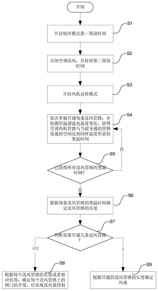
[0059] This embodiment provides another air supply control method. The air supply control method in this embodiment is applied to an air conditioner. The air conditioner has multiple air supply ducts controlled by air valves, and the air supply ducts supply air to different indoor space areas. The above-mentioned air conditioner includes an internal unit and an external unit, and also includes a control device, a storage device, a damper device, and the like.
[0060] image 3 It is a flow chart of the air supply control method according to another embodiment of the present invention, such as image 3 As shown, the method includes:
[0061] S1, turning on the cooling mode for the first preset time.
[0062] During specific implementation, when the installation position detection command of the air conditioner is input, the air conditioner will be turned on, and all air valves of the air conditioner can be opened to the maximum, and the cooling mode will be turned on for a pe...
PUM
 Abstract
Description
Claims
Application Information
 - Generate Ideas
- Intellectual Property
- Life Sciences
- Materials
- Tech Scout
- Unparalleled Data Quality
- Higher Quality Content
- 60% Fewer Hallucinations
Browse by: Latest US Patents, China's latest patents, Technical Efficacy Thesaurus, Application Domain, Technology Topic, Popular Technical Reports.
© 2025 PatSnap. All rights reserved.Legal|Privacy policy|Modern Slavery Act Transparency Statement|Sitemap|About US| Contact US: help@patsnap.com


