Roller type supporting leg, bridge swivel system and construction method
A roller-type, foot-supporting technology, which is applied in the direction of bridges, bridge construction, erection/assembly of bridges, etc., can solve the problem of not being able to control the static state of the roller trolley, and achieve the effect of reducing the probability of overturning
- Summary
- Abstract
- Description
- Claims
- Application Information
AI Technical Summary
Problems solved by technology
Method used
Image

Examples
Embodiment 1
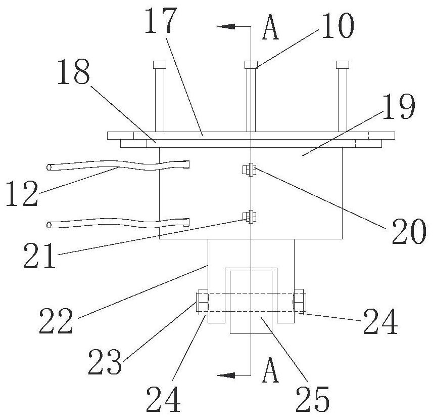
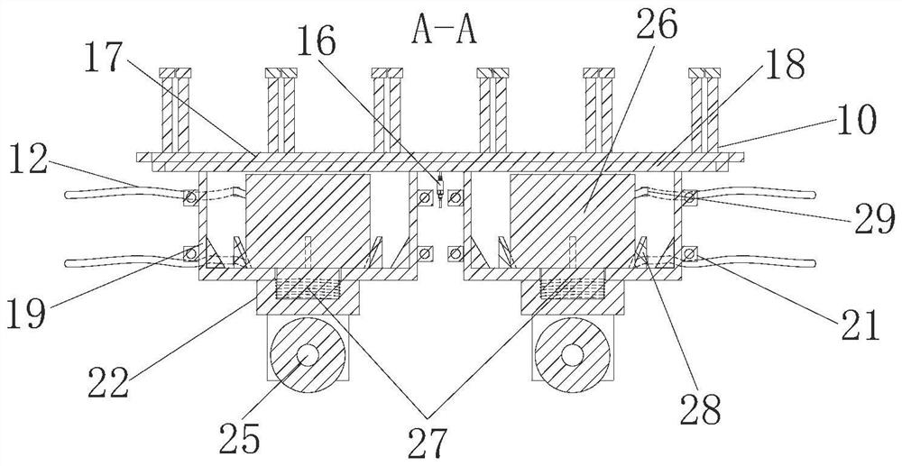
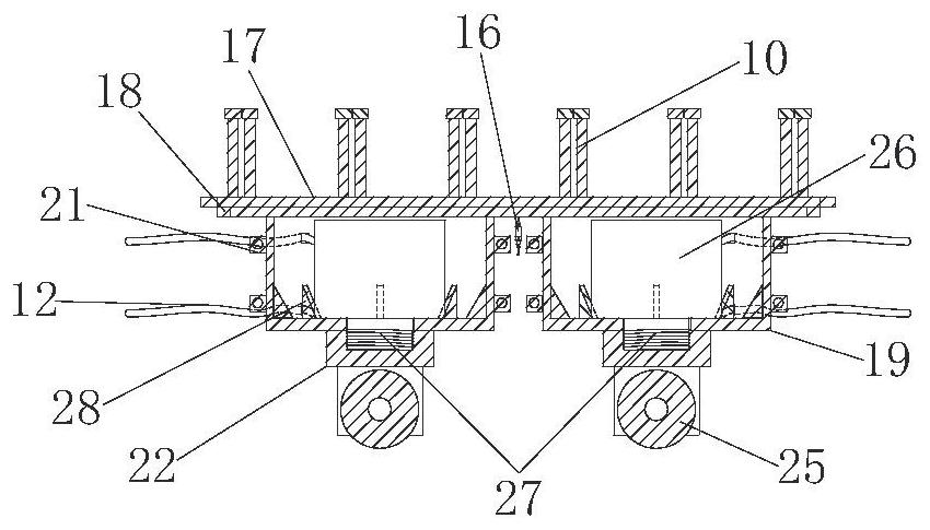
[0037] Such as Figure 1-Figure 5 As shown, this embodiment provides a roller-type stand, including a support shell, the lower part of which is connected to the rollers in rotation, the support shell is used to connect the lower end surface of the upper platform 3, and the rollers can move along the lower platform 5. The distance between the central axis of the roller and the upper end surface of the supporting shell can be adjusted.
[0038] It should be pointed out that in this embodiment, the roller-type support structures are used in pairs, that is, the attached figure 1 - attached Figure 5 Provided in is a schematic diagram of two roller support structures used together.
[0039] Described support shell comprises the first shell 19 that is fixed with upper platform 3, and the second shell 22 is arranged below the first shell 19, and the second shell 22 is connected with roller 25 rotation; The first shell 19 and A linear telescopic element is installed between the sec...
Embodiment 2
[0050] This embodiment provides a bridge swivel system. It can be understood that it should include the upper cap 3, the lower cap 5 and the swivel support 8 in the existing bridge swivel system. The upper surface of the lower cap 5 should be The traction cable 6 and the push jack 7 are set, and the cooperation of the traction cable and the push jack 7 is used to provide traction for the rotation of the bridge.
[0051] Specifically, the swivel system should also include the above-mentioned roller support feet 11, and a plurality of roller support feet 11 are arranged along the circumferential direction with the swivel support 8 as the center.
[0052] The upper end surface of the lower platform 5 surrounds the swivel support 8 with a limiting side plate 37, an annular slide groove 48 is formed on the inner wall of the limiting side plate 37, and a side surface with a vertical axis of rotation is installed on the side of the first housing. Guide wheel 35, side guide wheel 35 c...
Embodiment 3
[0060] This embodiment provides a bridge swivel method, utilizing the bridge swivel system described in Embodiment 2, comprising the following steps:
[0061] Step 1, complete the construction of the bridge swivel system.
[0062] Specifically, the construction of the bridge swivel system includes the following steps:
[0063] (a) Construction of the lower cap 5: According to the construction drawings, bind the steel bars of the lower cap 5, reserve the steel bars for the traction reaction seat 4, install the annular slideway 15, and the flatness should meet the specification requirements. The lower platform 5 adopts a vertical formwork, and concrete pouring and maintenance are carried out in two steps.
[0064] (b) Limiting side plate construction: After the construction of the upper cap 3 is completed, the limit side plate 37 is constructed on the outer edge of the upper cap 3, and the annular chute 48 is reserved before pouring the limit side plate, and the limit side plat...
PUM
 Abstract
Description
Claims
Application Information
 - Generate Ideas
- Intellectual Property
- Life Sciences
- Materials
- Tech Scout
- Unparalleled Data Quality
- Higher Quality Content
- 60% Fewer Hallucinations
Browse by: Latest US Patents, China's latest patents, Technical Efficacy Thesaurus, Application Domain, Technology Topic, Popular Technical Reports.
© 2025 PatSnap. All rights reserved.Legal|Privacy policy|Modern Slavery Act Transparency Statement|Sitemap|About US| Contact US: help@patsnap.com