Roller type support, bridge swivel system and construction method
A roller-type, swivel technology, applied in bridges, bridge construction, erection/assembly of bridges, etc., can solve problems such as the inability to control the static state of roller trolleys, and achieve the effect of reducing the probability of engineering accidents and increasing functions
- Summary
- Abstract
- Description
- Claims
- Application Information
AI Technical Summary
Problems solved by technology
Method used
Image

Examples
Embodiment 1
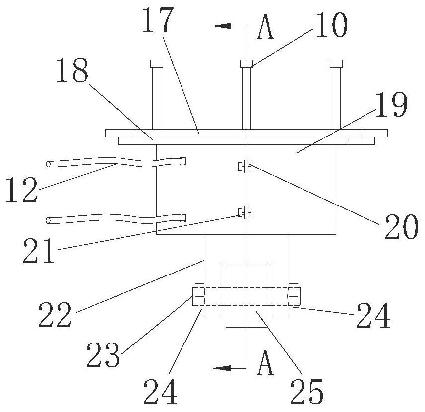
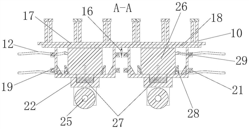
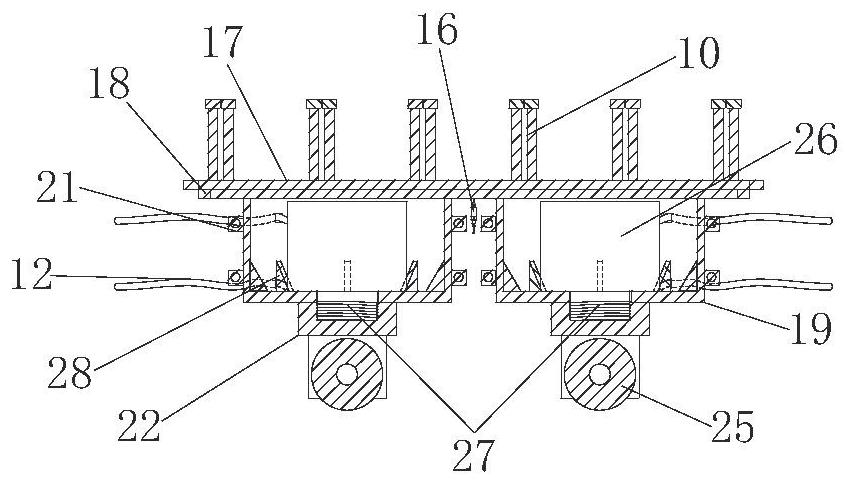
[0037] like Figure 1 - Figure 5 , The present embodiment provides a roller type legs, comprising a support housing, a lower housing supporting the roller rotatably connected to the support housing for connecting the upper end surface of the lower bearing base 3, the roller 5 is movable along the bearing platform walking on the end surface, the distance between the end faces on the central axis of the wheel support housing can be adjusted.
[0038] It is noted that, in this embodiment a roller-type leg structure in pairs, i.e., attached figure 1 Addition Figure 5 Is a schematic view of two roller type structure commonly used legs provided.
[0039] The support housing comprises a fixed table 3 and the first bearing housing 19, below the first housing 19 is provided with a second housing 22, the second housing 22 is connected to the rotation of the roller 25; a first housing 19 and the mounting a second housing member 22 has a linear stretch to adjust the distance between the first ...
Embodiment 2
[0050] This embodiment provides a bridge split system, which should be understood that the upper bearing platform 3, the downlay 5, and the splitter 8 in the existing bridge split system should include the upper surface of the lower platform 5. Set traction index 6 and top pusher top 7, provide traction to the split of the bridge with the traction index and the top push jack 7.
[0051] Specifically, the split system should also include the roller pin 11, and the plurality of roller pin 11 are centered on the rotor holder 8, along the circumferential direction.
[0052] The upper end surface of the lower stage 5 is surrounding the sprigon support 8, and the inner wall of the limit side plate 37 forms a ring chute 48 at the inner wall of the limit side plate 37, and the side surface of the first housing is mounted with a vertical side of the rotating axis. The guide wheel 35, the lateral guide wheel 35 can travel along the annular chute 48.
[0053] Specifically, the outer side sur...
Embodiment 3
[0060] In this embodiment, a bridge split system is provided, and the bridge split system described in Example 2 includes the following steps:
[0061] Step 1, complete the construction of the bridge split system.
[0062] Specifically, the construction of the bridge split system includes the following steps:
[0063] (a) Construction of the underlayer 5: According to the construction drawings, the underlying platform 5 steel is binding, the reinforcement of the traction reaction seat 4 is reserved, and the ring slide 15 is installed and the flatness should meet the specification requirements. The downstack 5 uses a mold, divided into concrete pouring, maintenance.
[0064] (b) Limit side plate construction: After the construction of the upper platform 3 is completed, the limit side plate 37 is applied at the outer edge of the upper platform 3, prior to the pouring limit side panel, the loop slide 48, the limit side panel 37 The voids between the upper platform 3 can ensure that t...
PUM
 Abstract
Description
Claims
Application Information
 - Generate Ideas
- Intellectual Property
- Life Sciences
- Materials
- Tech Scout
- Unparalleled Data Quality
- Higher Quality Content
- 60% Fewer Hallucinations
Browse by: Latest US Patents, China's latest patents, Technical Efficacy Thesaurus, Application Domain, Technology Topic, Popular Technical Reports.
© 2025 PatSnap. All rights reserved.Legal|Privacy policy|Modern Slavery Act Transparency Statement|Sitemap|About US| Contact US: help@patsnap.com