Positioning method for mold platen on preformed part production line

A positioning method and technology of prefabricated parts, applied in electrical components, manufacturing tools, mold auxiliary parts, etc., can solve the problems of increasing the difficulty of research and development, cost input, affecting production efficiency, etc., and achieve flexible debugging, low cost, and automation. Effect

Active Publication Date: 2020-10-16
CHINA MINSHENG ZHUYOU
View PDF6 Cites 2 Cited by
  • Summary
  • Abstract
  • Description
  • Claims
  • Application Information

AI Technical Summary

Problems solved by technology

[0004] For example, the relevant technological process in the production process of prefabricated wall panels: cleaning the mold table, brushing the release agent - placing the mold by the robot (station A) - placing the steel skeleton and mesh - placing the embedded parts (station B) - —Pouring concrete, but adding processes such as "placing steel skeleton and mesh" and "placing embedded parts" at the mold-setting station will affect production efficiency and increase the difficulty of research and development and cost investment. Therefore, it is necessary to integrate The positioning accuracy of the mold table is improved, so that the mold setting accuracy can be continued in the process of placing steel bars and embedded parts

Method used


Image

  • Positioning method for mold platen on preformed part production line
  • Positioning method for mold platen on preformed part production line
  • Positioning method for mold platen on preformed part production line

Examples


Embodiment Construction

[0047] The present invention will be described in detail below in conjunction with the accompanying drawings. The description in this part is only exemplary and explanatory, and should not have any limiting effect on the protection scope of the present invention. In addition, those skilled in the art can make corresponding combinations of features in the embodiments in this document and in different embodiments according to the descriptions in this document.

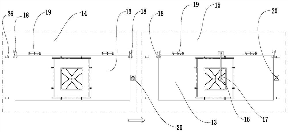
[0048] Embodiments of the present invention are as follows, as figure 1 , a method for positioning mold table 13 on a prefabricated part production line, comprising the steps of:

[0049] (1) The mold table 13 flows along the prefabricated part production line to the station A14, and the visual recognition mechanism 18 takes pictures and obtains the position information of the mold table 13 at the station A14, and sends the acquired mold table 13 position information to the control processing module;

[0050] (2) After ...


PUM


Abstract

The invention relates to a positioning method for a mold platen on a preformed part production line. The method includes the steps that (1) the position information of the mold platen at station A isobtained and sent to control processing modules; (2) the mold platen is moved to station B, and the position information of the mold platen at station B is obtained and sent to the control processingmodules; (3) relative offset data of the position of the mold platen at the station B relative to the position of the mold platen at the station A is calculated and obtained by the control processingmodules; and (4) the control processing modules control a rectifying mechanism mounted above the station B to move, the rectifying mechanism drives a projecting mechanism to move to a designated position, the projecting mechanism projects drawing information of the prefabricated part in the form of laser lines to the mold platen located at the station B, and the laser lines projected is corresponded to an operation position at the situation A. The positioning method for the mold platen on the preformed part production line can accordingly adjust and correct the position information of the moldplaten, and realize the high-precision coincidence of the mold platen at different position coordinates of stations, so as to be beneficial to realize the automation of the production of the preformed part.

Description

technical field [0001] The invention belongs to the technical field of PC component production, and in particular relates to a mold table positioning method on a prefabricated part production line. Background technique [0002] The production of concrete prefabricated parts often requires the use of special mold tables. At present, in the production of PC components, the circulation of mold tables on the production line basically relies on the support wheel rib (rim) to prevent deviation and limit, while along the conveying direction, it relies on sensors. (proximity switch, etc.) to control the start and stop positioning of the mold table, the positioning deviation in the width direction is generally more than 10mm, and the positioning error in the conveying direction can reach 20mm. [0003] With the upgrading of factory automation, many production lines are undergoing automatic transformation one after another, so the positioning accuracy requirements for mold table trans...

Claims


Application Information

Patent Timeline
Patent Type & Authority Applications(China)
IPC IPC(8): B28B17/00B28B7/00H04N5/225
CPCB28B17/00B28B17/0063B28B17/0081B28B7/0032B28B7/0002H04N23/57
Inventor 杨军宏邓亚湘习可陈明黄岸
Owner CHINA MINSHENG ZHUYOU
Why Eureka
Try Eureka