
Metal workpiece machining device utilizing thread cutting

A metal workpiece and processing device technology, applied in the field of metal workpiece processing devices, can solve the problems of adjusting the water output of the workpiece, poor cutting lines, and affecting thread formation, etc., to achieve good clamping effect, good lines, and avoid shaking Effect

Inactive Publication Date: 2020-10-16
缪笑燕
View PDF0 Cites 3 Cited by
  • Summary
  • Abstract
  • Description
  • Claims
  • Application Information

AI Technical Summary

Problems solved by technology

[0003] When performing thread cutting, the bolt workpiece is generally fixed and clamped inside the chuck, and then an irregular screwdriver is used to thread the bolt. During the cutting process, due to the high-speed rotation of the chuck, often The cutting lines are not good, which affects the formation of the thread, and in the process of thread cutting, it is often necessary to cool the surface of the workpiece with a spray system, and the water output cannot be adjusted according to the workpiece itself, and sometimes a certain amount of time will be wasted. Water quality, therefore, in view of this, research and improve the existing structure and defects, and provide a metal workpiece processing device using thread cutting, in order to achieve more practical purposes

Method used


Image

  • Metal workpiece machining device utilizing thread cutting
  • Metal workpiece machining device utilizing thread cutting
  • Metal workpiece machining device utilizing thread cutting

Examples


Embodiment Construction

[0024] The present invention will be further described below in conjunction with accompanying drawing:

[0025] as attached figure 1 to attach Figure 8 Shown:

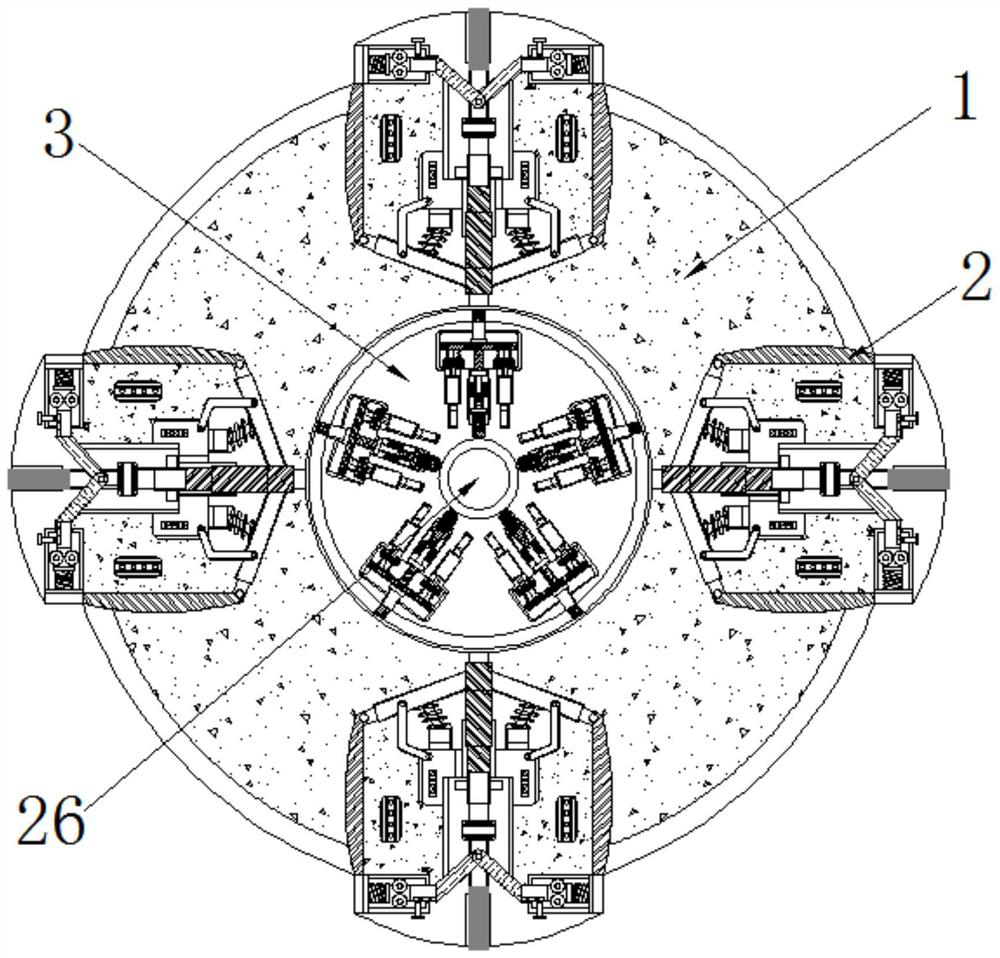
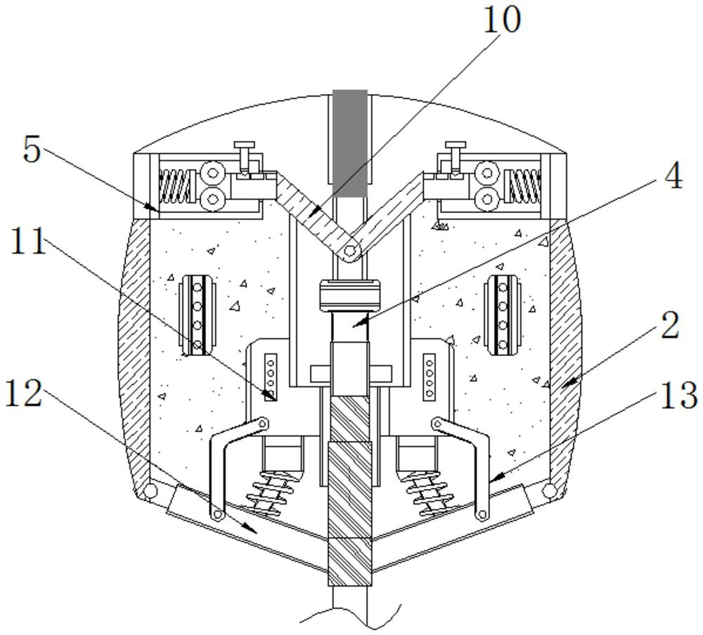
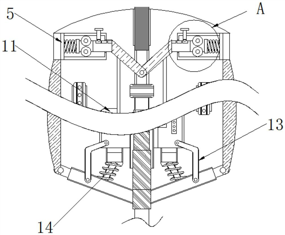
[0026] The invention provides a metal workpiece processing device utilizing thread cutting, comprising a chuck 1, an installation frame 2 is arranged inside the chuck 1, an adjusting plate 3 is arranged inside the chuck 1, and the inner wall of the installation frame 2 is movably connected with Sliding column 4, the inner wall of mounting bracket 2 is fixedly connected with limit seat 5, the interior of limit seat 5 is connected with limit spring 6, and one side of limit spring 6 is movably connected with limit column 7, and the surface of limit column 7 is opened There is a card slot 8, the inside of the card slot 8 is movably connected with a card post 9, the shape of the card slot 8 is compatible with the shape of the card post 9, the diameters of the adjacent card slots 8 are equidistantly arranged, and the oute...


PUM


Abstract

The invention belongs to the technical field of thread cutting, and particularly relates to a metal workpiece machining device utilizing thread cutting. A mounting frame is arranged in a chuck, an adjusting plate is arranged in the chuck, a sliding column is movably connected to the inner wall of the mounting frame, a limiting seat is fixedly connected to the inner wall of the mounting frame, a limiting spring is movably connected to the interior of the limiting seat, a limiting column is movably connected to one side of the limiting spring, a clamping groove is formed in the surface of the limiting column, a clamping column is movably connected to the interior of the clamping groove, an adjusting rod is rotationally connected to the position, located on the surface of the sliding column,of one end of the limiting column, the adjusting rod penetrates through the interior of a supporting seat, and a first rotating rod is rotationally connected to the surface of the sliding column and located on one side of the mounting frame. During use, the water outlet amount of a water outlet pipe can be automatically controlled, the phenomenon that much water is wasted during treatment is avoided, and convenience is brought to thread cutting of a bolt column.

Description

technical field [0001] The invention belongs to the technical field of thread cutting, in particular to a metal workpiece processing device utilizing thread cutting. Background technique [0002] There are many methods for forming external threads on the outer peripheral surface of a shaft member. One of them is the thread turning method. While rotating the shaft member to be processed at a low speed, it rotates one revolution along the axis direction. It feeds the amount of one lead of the thread to be formed. On the other hand, the cutting edge of one or more cutting inserts is on a circular track that is larger than the outer diameter of the shaft member and inscribed with the shaft member. Rotate at high speed in the same direction of rotation, and perform intermittent cutting on the circular orbit with the amount of cut corresponding to the thread teeth. [0003] When performing thread cutting, the bolt workpiece is generally fixed and clamped inside the chuck, and the...

Claims


Application Information

Patent Timeline
Patent Type & Authority Applications(China)
IPC IPC(8): B23G1/44B23G11/00B23Q3/08B23Q11/10B23Q11/00
CPCB23G1/44B23G11/00B23Q3/08B23Q11/0032B23Q11/0042B23Q11/10
Inventor 缪笑燕
Owner 缪笑燕
Learn More