
Intelligent sliding device for hospital bed during infusion

A sliding device, intelligent technology, applied in non-electric variable control, hypodermic injection equipment, flow control and other directions, can solve the problem of inaccurate control, need manual operation, etc., to achieve the effect of reducing flow

Inactive Publication Date: 2020-10-16
CHONGQING MEDICAL & PHARMA COLLEGE
View PDF6 Cites 0 Cited by
  • Summary
  • Abstract
  • Description
  • Claims
  • Application Information

AI Technical Summary

Problems solved by technology

[0004] The purpose of the present invention is to solve the problem of needing manual operation and unable to control accurately, and the proposed intelligent sliding device for bed infusion

Method used


Image

  • Intelligent sliding device for hospital bed during infusion
  • Intelligent sliding device for hospital bed during infusion
  • Intelligent sliding device for hospital bed during infusion

Examples


Embodiment 1

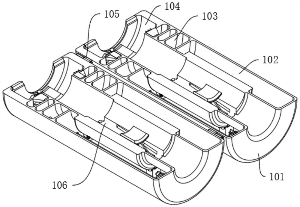
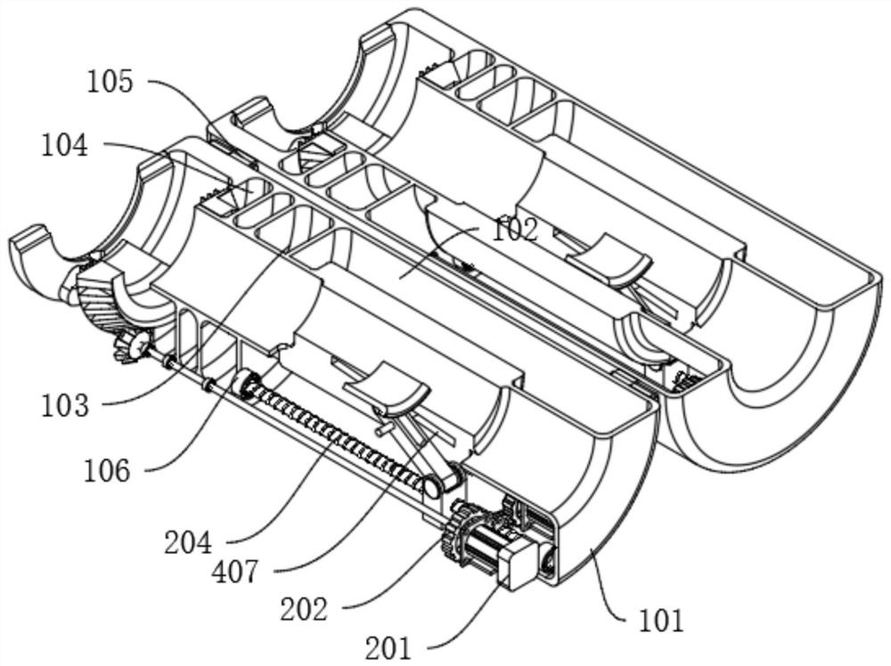
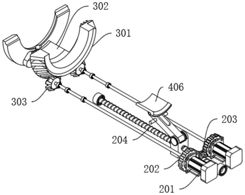
[0025] The intelligent sliding device for hospital bed infusion includes: a semi-arc housing 101, a driving compartment 102, a partition compartment 103 and a fixed compartment 104. The semi-arc housing 101 is provided with two groups, and the semi-arc housing 101 is movably connected by a hinge 105. The interior of the arc-shaped housing 101 is provided with a fixed bin 104, a partition bin 103, and a driving bin 102 in sequence from left to right. A moving slot 106 is arranged in the middle of the driving bin 102, and inclined fixed slots are arranged on the front and rear sides of the inner wall of the moving slot 106. 107, the right side of the drive compartment 102 is provided with a dual-motor drive mechanism, the left side of the dual-motor drive mechanism is fixedly connected with the infusion fixation mechanism, and the infusion fixation mechanism is movably installed inside the fixed compartment 104. The lower side of the fixing mechanism is threaded, the lower side o...

Embodiment 2

[0031] Embodiment 2: Based on Embodiment 1, the difference is:

[0032]The one-way moving and fixing mechanism includes: a moving block 401, a torsion spring 402, a rotating shaft 403, a rotating rod 404, a transmission shaft 405, a friction fixing block 406 and a limit rod 407, and the rotating screw rod 204 is screwed with a moving block 401, The interior of the upper side of the moving block 401 is movably connected with the front and rear ends of the rotating shaft 403. The front and rear ends of the rotating shaft 403 are fixedly equipped with a torsion spring 402, and the other end of the torsion spring 402 is fixedly connected with the inner wall of the moving block 401. The lower end of 404 is fixedly connected, the lower end of the rotating rod 404 is fixedly connected with the front and rear ends of the transmission shaft 405, the upper side of the middle part of the friction moving block 406 is movably connected with the middle part of the transmission shaft 405, and...


PUM


Abstract

The invention discloses an intelligent sliding device for a hospital bed during infusion, and belongs to the field of plastic cement pipeline butting. According to the intelligent sliding device for ahospital bed during infusion, a dual-motor driving mechanism which is arranged is used for driving the device to wholly drive, the device is fixed around an infusion hose, then a servo motor locatedon the front side is started to rotate forwards to drive a transmission ratchet wheel to rotate, a semi-gear ring is driven to rotate, a movable opening fixing block is driven to move towards an axlecenter along a spacing groove, the device is fixed to an infusion bottle opening and is fastened, then the servo motor on the front side is started to rotate in a reverse direction, a rotating ratchetwheel is driven to rotate, a transmission gear is driven to rotate, and a rotating lead screw is driven to move, so that a unidirectional moving and fixing mechanism is driven to move forwards alongthe rotating lead screw, move along the infusion hose and move along a rotating rod, fixing grooves in two sides can enable the distance between friction fixed blocks to be decreased, and flow of theinfusion hose is decreased.

Description

technical field [0001] The invention relates to the field of infusion control devices, in particular to an intelligent sliding device for hospital bed infusion. Background technique [0002] With the development of the economy, the resources of medical personnel are insufficient, and the staff is tense. In many cases, it is impossible to take care of patients without leaving. The contradiction between outpatient and inpatient patients needing transfusion and tense human resources is increasing day by day. There is an urgent need for smart medical or smart care equipment. At present, the monitoring for ordinary infusion is generally a professional monitor, which can monitor multiple functional data, has a large size, complicated operation settings, and requires professional medical personnel to operate. It is generally used for the monitoring of critically ill patients, and is not suitable for Ordinary patients and their families use. In addition, there are also individual...

Claims


Application Information

Patent Timeline
Patent Type & Authority Applications(China)
IPC IPC(8): A61M5/168
CPCA61M5/16813A61M2205/3334
Inventor 廖世英雷道海易利华唐梦忆
Owner CHONGQING MEDICAL & PHARMA COLLEGE
Learn More