
Modal testing device and modal testing method for flexible structure

A modal test and flexible structure technology, which is applied in the testing of machines/structural components, measuring devices, vibration testing, etc., can solve the problem of deviation between test results and real values, and eliminate the vibration exciter connecting rod and vibration exciter effect, the effect of improving accuracy

Inactive Publication Date: 2020-10-13
CHINA AIRPLANT STRENGTH RES INST
View PDF6 Cites 9 Cited by
  • Summary
  • Abstract
  • Description
  • Claims
  • Application Information

AI Technical Summary

Problems solved by technology

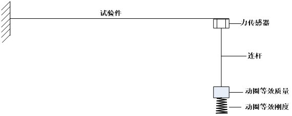
[0002] In structural vibration testing, it is often necessary to use a vibrator to excite the structure. The vibrator is often connected to the structure by a connecting rod. Since the axial force needs to be transmitted, the connecting rod needs to have a large axial stiffness and a small Lateral stiffness is used to minimize the influence of the connecting rod on the test results during the process of force transmission, but for the connecting rod structure, the lateral stiffness cannot be too small, so the impact on the test results of the structure will inevitably exist. The test of the structure is more obvious, which will cause the test results to deviate significantly from the true value. Therefore, if you want to use the exciter to excite the flexible structure in the ground vibration test, you must reduce the influence of the additional characteristics of the exciter and the connecting rod as much as possible.

Method used


Image

  • Modal testing device and modal testing method for flexible structure
  • Modal testing device and modal testing method for flexible structure
  • Modal testing device and modal testing method for flexible structure

Examples


Embodiment Construction

[0033] In order to make the purpose, technical solution and advantages of the application more clear, the technical solution in the embodiment of the application will be described in more detail below in conjunction with the drawings in the embodiment of the application. In the drawings, the same or similar reference numerals denote the same or similar elements or elements having the same or similar functions throughout. The described embodiments are some, but not all, embodiments of the application. The embodiments described below by referring to the figures are exemplary, and are intended to explain the present application, and should not be construed as limiting the present application. Based on the embodiments in this application, all other embodiments obtained by persons of ordinary skill in the art without creative efforts fall within the protection scope of this application. Embodiments of the present application will be described in detail below in conjunction with th...


PUM


Abstract

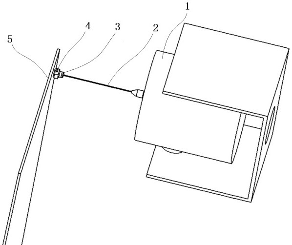
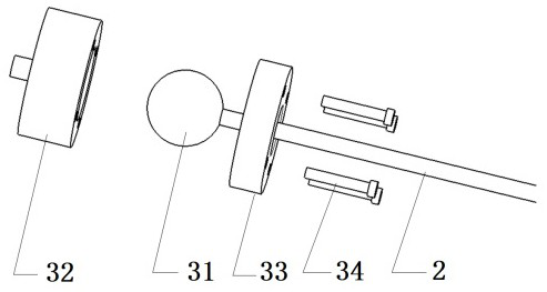
The invention belongs to the technical field of vibration testing, and particularly relates to a modal testing device and a modal testing method for a flexible structure. The modal testing device comprises a vibration exciter, a connecting rod fixed to a top end of a vibration exciter output shaft in a vertical direction, a force sensor connected to the top end of the connecting rod through a ballhead hinge device and used for measuring an exciting force, a flexible plate-shaped test piece, and an acceleration sensor, wherein one end of the flexible plate-shaped test piece is fixed at a fixedpoint in a test area, and the bottom surface of the other end of the flexible plate-shaped test piece abuts against the top of the force sensor; and the acceleration sensor is arranged on the test piece and is used for testing a response signal. According to the modal testing device and the modal testing method for the flexible structure, by combining the ball head hinge device and the force sensor, an influence of axial rigidity and bending rigidity of the connecting rod on the structure test result is eliminated, and the influence of a vertical axial force on the structure is relatively small so that the influence of the vibration exciter connecting rod and the vibration exciter can be basically eliminated, and the precision of the test result, especially the test result of the flexiblestructure, is improved.

Description

technical field [0001] The application belongs to the technical field of vibration testing, and in particular relates to a modal testing device and a modal testing method for flexible structures. Background technique [0002] In structural vibration testing, it is often necessary to use a vibrator to excite the structure. The vibrator is often connected to the structure with a connecting rod. Since the axial force needs to be transmitted, the connecting rod needs to have a large axial stiffness and a small Lateral rigidity in order to minimize the influence of the connecting rod on the test results in the process of force transmission, but for the connecting rod structure, the lateral rigidity cannot be too small, so the influence on the test results of the structure will inevitably exist. The test of the structure is more obvious, which will cause the test results to deviate significantly from the true value. Therefore, if you want to use the exciter to excite the flexible ...

Claims


Application Information

Patent Timeline
IPC IPC(8): G01M7/02
CPCG01M7/025
Inventor 王彬文宋巧治李晓东刘小川李智劳
Owner CHINA AIRPLANT STRENGTH RES INST
Learn More