deep sense light emitting device
A light-emitting device and a deep technology, which is applied in lighting and heating equipment, optical signals, transportation and packaging, etc., can solve the problems of cost increase, body sheet metal stamping depth limit, and the depth cannot be made too deep, so as to save cost and cost The effect of low cost and easy mass production
- Summary
- Abstract
- Description
- Claims
- Application Information
AI Technical Summary
Problems solved by technology
Method used
Image
Examples
Embodiment 1
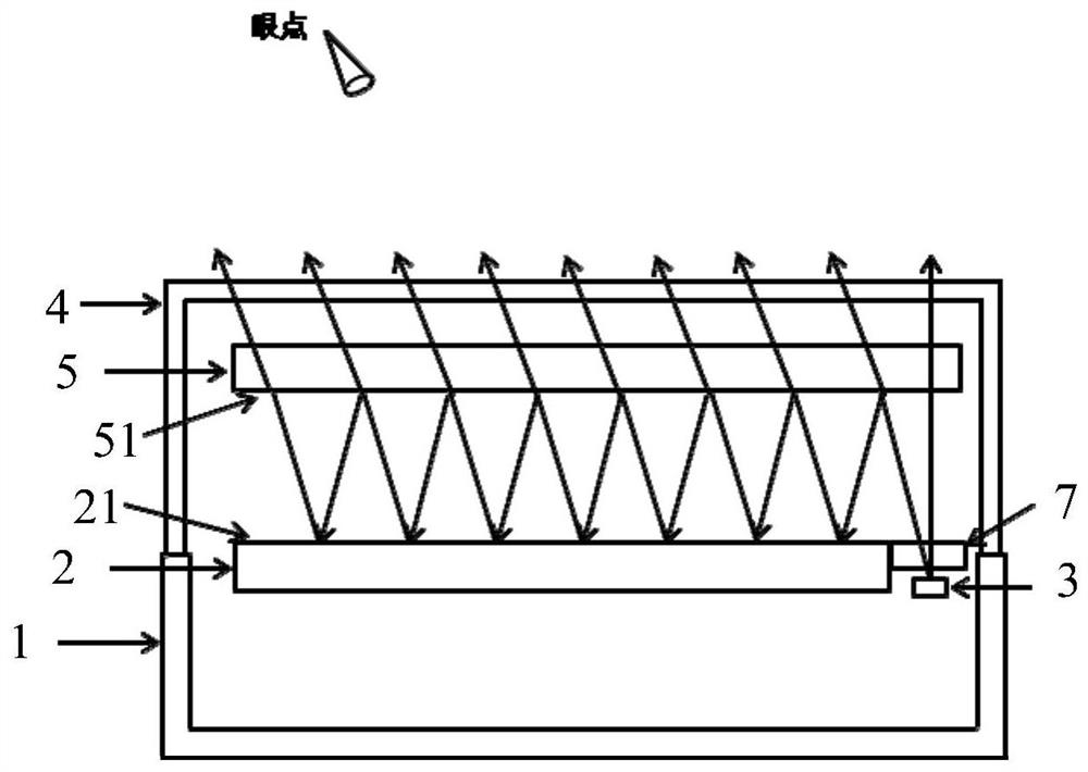
[0037] like figure 1 Shown is a schematic structural diagram of the depth-sensing light-emitting device in Embodiment 1.
[0038] A light-emitting device with deep feeling, including a lampshade, a lamp housing 1, a bezel 2 and LED3, the lampshade includes an outer lampshade 4 and an inner lampshade 5, the outer lampshade 4 is fastened with the lamp housing 1, and the bezel 2 and LED3 are installed on the outer lampshade 4 and the lamp housing In the cavity of 1, the inner surface of the inner lampshade 5 is provided with a dichroic film 51, the outer surface of the bezel 2 is a reflective surface 21, the dichroic film 51 and the reflective surface 21 are arranged at relative intervals, and the LED3 is located on the bezel 2 Beside, LED3 emits light toward the light-splitting film 51, a small part of the light passes through the light-splitting film 51 and the inner lampshade 5, most of the light is reflected by the light-splitting film 51, and shoots to the light-reflecting s...
Embodiment 2
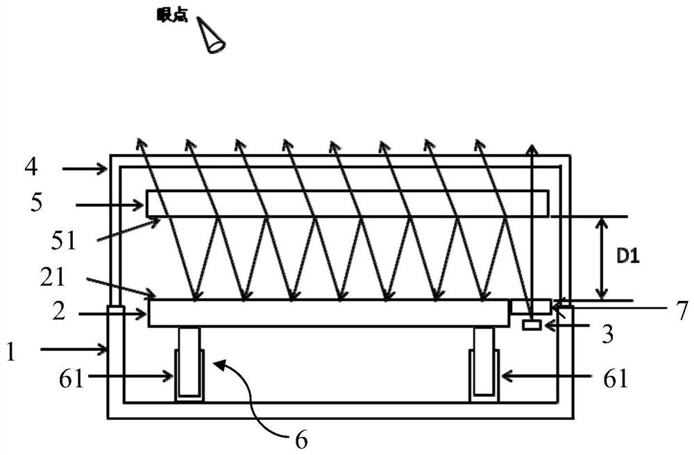
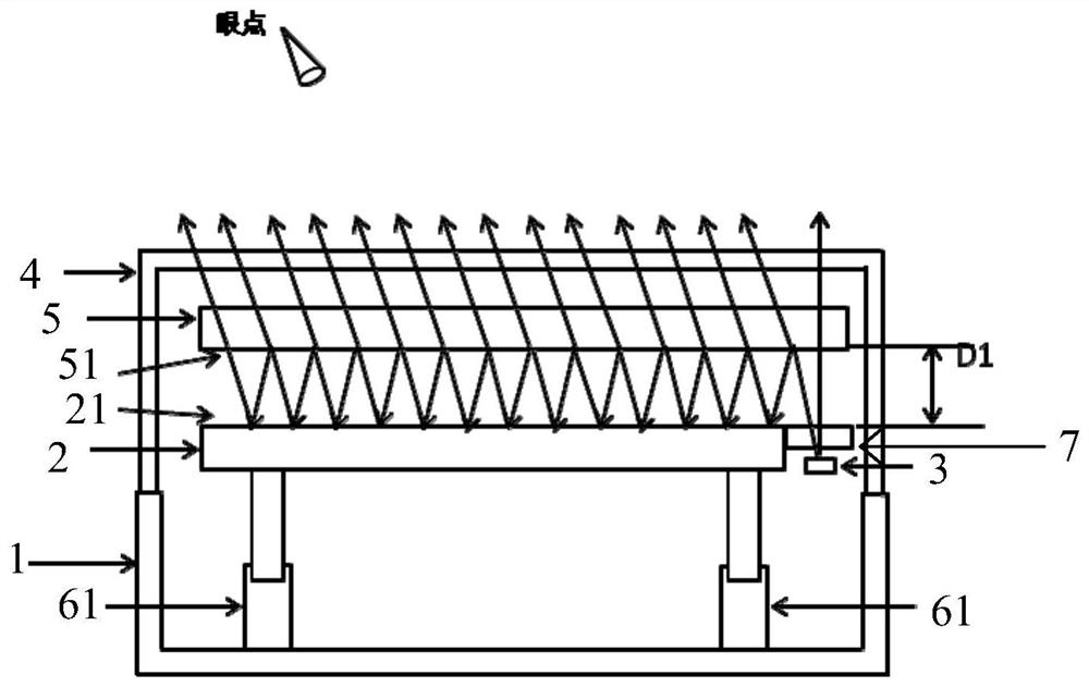
[0050] like Figure 2-3 Shown is a schematic structural diagram of the depth-sensing light-emitting device in Embodiment 2.
[0051] The inner surface of the bezel 2 is provided with a driving unit 6 for driving the bezel to move toward or away from the inner lampshade 5 .
[0052] Furthermore, the inner lampshade 5 and the bezel 2 are parallel to each other, and the drive unit 6 includes two lifting motors 61, which are respectively installed at the two ends of the bezel 2. The two lifting motors 61 are synchronously telescopic. The bezel 2 moves towards or away from the inner shade 5 .
[0053] like figure 2 As shown, in the initial state, the distance between the dichroic film 51 and the reflective surface 21 is D1.
[0054] like image 3 As shown, when the lifting motor 61 extends toward the inner lampshade 5, the bezel 2 is pushed toward the inner lampshade 5, and D1 becomes smaller. As D1 becomes smaller, the number of times the light is reflected increases, and the...
Embodiment 3
[0058] like Figure 4-5 As shown, it is a schematic structural diagram of the depth-sensing light-emitting device in the third embodiment.
[0059] The difference from the second embodiment is that there is only one lifting motor 61 in the third embodiment, and the lifting motor 61 is installed on one end of the bezel 2, and the other end of the bezel 2 is fixedly connected by a rotating shaft 62, and the lifting motor 61 drives the bezel One end of 2 rotates around the rotating shaft 62.
[0060] like Figure 4 As shown, in the initial state, the inner lampshade 5 and the bezel 2 are parallel to each other.
[0061] like Figure 5 As shown, the lifting motor 61 is raised, so that the decorative ring 2 at the left end moves toward the inner lampshade 5 , and the right end of the decorative ring 2 rotates around the rotating shaft 62 .
[0062] Figure 5 The D1 at the far right in the middle remains unchanged. From right to left, the number of reflections increases, and th...
PUM
 Abstract
Description
Claims
Application Information
 - R&D Engineer
- R&D Manager
- IP Professional
- Industry Leading Data Capabilities
- Powerful AI technology
- Patent DNA Extraction
Browse by: Latest US Patents, China's latest patents, Technical Efficacy Thesaurus, Application Domain, Technology Topic, Popular Technical Reports.
© 2024 PatSnap. All rights reserved.Legal|Privacy policy|Modern Slavery Act Transparency Statement|Sitemap|About US| Contact US: help@patsnap.com


