
A pneumatic valve detection device

A technology of detection device and pneumatic valve, applied in valve device, measurement device, valve operation/release device, etc., can solve the problems of pneumatic valve being difficult to apply to fluid pipeline, difficult to find faults in time, and inconvenient for maintenance and so on.

Active Publication Date: 2021-12-24
SOUTHWEST UNIV
View PDF0 Cites 0 Cited by
  • Summary
  • Abstract
  • Description
  • Claims
  • Application Information

AI Technical Summary

Problems solved by technology

[0002] Traditional pneumatic valves are difficult to apply to fluid pipelines with high flow rate and high pressure, and are easy to be damaged. It is difficult to find out in time when a fault occurs, and it is inconvenient to repair

Method used


Image

  • A pneumatic valve detection device
  • A pneumatic valve detection device
  • A pneumatic valve detection device

Examples


Embodiment Construction

[0011] In order to make the purpose, technical solutions and advantages of the embodiments of the present invention clearer, the technical solutions in the embodiments of the present invention will be clearly and completely described below in conjunction with the drawings in the embodiments of the present invention. Obviously, the described embodiments It is a part of embodiments of the present invention, but not all embodiments. Based on the embodiments of the present invention, all other embodiments obtained by persons of ordinary skill in the art without creative efforts fall within the protection scope of the present invention.

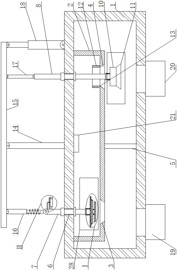
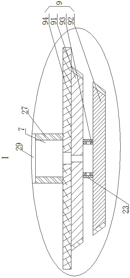
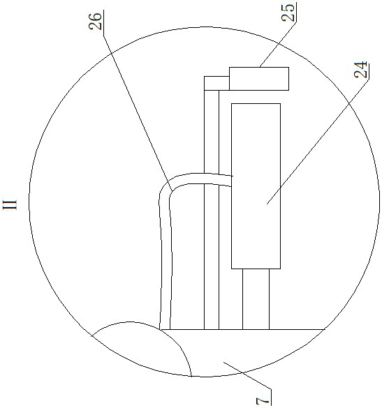
[0012]A pneumatic valve detection device, as shown in the figure, includes a box body 1, a U-shaped plate 2 is arranged in the box body 1, and the upper end and the front and rear ends of the U-shaped plate 2 are sealed and fixedly connected with the inner wall of the box body 1. A first tapered hole 3 is provided on the left side of the bottom of...


PUM


Abstract

A pneumatic valve detection device, including a box body, a U-shaped plate is arranged in the box body, the upper end and the front and rear ends of the U-shaped plate are sealed and fixedly connected with the inner wall of the box, and a first tapered hole is opened on the left side of the bottom of the U-shaped plate , the second tapered hole on the right side of the bottom of the U-shaped plate, the small-diameter end of the first tapered hole faces downwards, and the small-diameter end of the second tapered hole faces upwards, fixedly installed between the middle of the bottom of the U-shaped plate and the bottom of the box The dividing plate and the top of the box corresponding to the first tapered hole and the second tapered hole are all provided with guide holes, and the first vertical shaft is installed in the guide hole on the left side. Through the wonderful design and double-plug closure system of the present invention, if one or both of the two tapered holes fails to seal, the pressure sensor detects that the pressure is unstable and will transmit the signal to the control system to give the staff an early warning and realize Automatic detection, reminding personnel to overhaul, and also has the advantages of good sealing effect, automatic buffer function, and high service life.

Description

technical field [0001] The invention belongs to the technical field of valves, in particular to a pneumatic valve detection device. Background technique [0002] Traditional pneumatic valves are difficult to be used in fluid pipelines with high flow rate and high pressure, and are easily damaged. When a fault occurs, it is difficult to find it in time and it is inconvenient to repair. Contents of the invention [0003] The invention provides a pneumatic valve detection device to solve the defects in the prior art. [0004] The present invention is achieved through the following technical solutions: [0005] A pneumatic valve detection device, including a box body, a U-shaped plate is arranged in the box body, the upper end and the front and rear ends of the U-shaped plate are sealed and fixedly connected with the inner wall of the box, and a first tapered hole is opened on the left side of the bottom of the U-shaped plate A second tapered hole is opened on the right side...

Claims


Application Information

Patent Timeline
Patent Type & Authority Patents(China)
IPC IPC(8): F16K1/38F16K1/42F16K1/32F16K27/02F16K31/122F16K37/00G01L11/00
CPCF16K1/38F16K1/42F16K1/32F16K27/0254F16K31/122F16K37/00G01L11/00
Inventor 张渝刘声潘东波
Owner SOUTHWEST UNIV
Learn More