


Quick Research
Generate reliable direction feasibility study reports for your R&D in just a few steps.

Technical Q&A
Discover and master advanced knowledge NOW. Basics, ideas, possibilities, all at once.

Find Solutions
As an expert in R&D theories, this can generate solutions to your technical problems instantly.

Evaluate Feasibility
Analyze your overall solution with one click, know your potential R&D risks in advance.

Monitor Landscape
Get weekly tech updates, stay abreast of the latest tech innovations and key insights.
Engine crankcase ventilation installation OBD diagnostic method based on electrical circuit
A technology for crankcase ventilation and diagnosis method, which is applied to crankcase ventilation, engine components, machines/engines, etc., can solve problems such as imprecise decision logic and no visual warning system, and achieve rigorous logic setting and fault judgment accuracy. High, avoid the effect of fault false trigger
- Summary
- Abstract
- Description
- Claims
- Application Information
AI Technical Summary
Problems solved by technology
Method used
Image

Examples
Embodiment 1
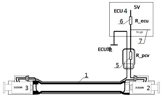
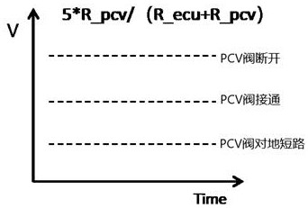
[0065] An OBD diagnosis method for an engine crankcase ventilation device based on an electric circuit, the OBD diagnosis method for an engine crankcase ventilation device is based on a crankcase ventilation device detection circuit, and the detection circuit includes: a ventilation pipe 1, a first contact switch 2, a second Two contact switches 3 and the engine controller 4, the two ends of the ventilation pipe 1 are respectively press-fitted with the switch contacts of the first contact switch 2 and the second contact switch 3, and one end of the first contact switch 2 is connected in sequence After being connected with PCV resistance 5 and ECU resistance 6, it is connected with the 5 volt DC power supply in the engine controller 4, and the other end of the first contact switch 2 is connected with the ECU in the engine controller 4 after the second contact switch 3 is connected in series. The ground phase is connected, and a PVC voltage detection point 7 connected to the sign...
Embodiment 2
[0080] Embodiment 2 is basically the same as Embodiment 1, and its difference is:
[0081] The connecting wires of the first contact switch 2 and the second contact switch 3 are pre-embedded outside the ventilation pipe 1. When the ventilation pipe 1 is installed normally, the first contact switch 2 and the second contact switch 3 are all in a closed state. The second contact switch 3 was disconnected when the left end of 1 fell off, and the first contact switch 2 was disconnected when the right end of the ventilation pipe 1 fell off.
Embodiment 3
[0083] Embodiment 3 is basically the same as Embodiment 2, and its difference is:
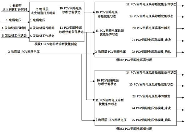
[0084] The ignition key opening time refers to the time when the ignition key is placed in the ON gear; the engine running time refers to the duration of the engine starting from the stop state, passing through the starting state, and the engine speed is greater than the calibration threshold of the running state; the engine working state , judged according to the position of the ignition key and the engine speed, divided into four states: stop, start, run, and flameout; the ignition key opening time threshold, engine running time threshold, battery voltage minimum threshold and battery voltage maximum threshold are all set The value can be changed according to different models; the high threshold of PCV circuit voltage and the low threshold of PCV circuit voltage are set voltage values, which can be changed according to different models; the setting of high PCV circuit voltage fault_pending dur...
PUM
 Abstract
Description
Claims
Application Information
 - R&D Engineer
- R&D Manager
- IP Professional
- Industry Leading Data Capabilities
- Powerful AI technology
- Patent DNA Extraction
Browse by: Latest US Patents, China's latest patents, Technical Efficacy Thesaurus, Application Domain, Technology Topic, Popular Technical Reports.
© 2024 PatSnap. All rights reserved.Legal|Privacy policy|Modern Slavery Act Transparency Statement|Sitemap|About US| Contact US: help@patsnap.com