An infusion tube fatigue detection device

A detection device and fatigue technology, applied in the medical field, can solve the problems of inaccurate flow rate, complicated installation, inconvenient assembly and production, etc., and achieve the effects of increasing the reliability of judgment, accurate detection results, and precise infusion flow rate

Active Publication Date: 2021-05-28
深圳普博腾迈医疗科技有限公司
View PDF9 Cites 0 Cited by
  • Summary
  • Abstract
  • Description
  • Claims
  • Application Information

AI Technical Summary

Problems solved by technology

This structure makes the space near the infusion pipeline narrow and inconvenient to directly measure its fatigue degree, which will increase the complexity and cost of the design and affect the reliability of the infusion
For example, using a photoelectric detection device to directly measure the infusion pipeline, first of all, the installation is relatively complicated, and the infusion pipeline and the liquid in the pipeline have different light transmittances. Based on the influence of light transmittance, the feedback of this detection scheme The electrical signal does not correctly reflect the fatigue of the pipeline
[0003] One of these solutions is to use empirical values ​​to judge pipeline fatigue and compensate for flow velocity, but there are always differences in different pipelines, and the actual value will always deviate from the empirical value, which leads to the flow velocity in practical applications. Not allowed; Another direct fatigue detection method for infusion pipelines is also limited by the structural space, which is inconvenient for assembly and production, and the detection accuracy of the photoelectric detection principle is not good.

Method used


Image

  • An infusion tube fatigue detection device
  • An infusion tube fatigue detection device
  • An infusion tube fatigue detection device

Examples


Embodiment Construction

[0026] The following will clearly and completely describe the technical solutions in the embodiments of the present invention with reference to the accompanying drawings in the embodiments of the present invention. Obviously, the described embodiments are only some, not all, embodiments of the present invention. Based on the embodiments of the present invention, all other embodiments obtained by persons of ordinary skill in the art without creative work, any modifications, equivalent replacements, improvements, etc., shall be included in the protection scope of the present invention Inside.

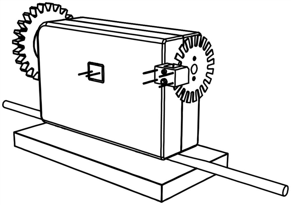
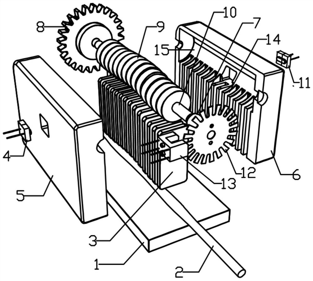
[0027] Such as Figure 1 to Figure 7 As shown, the infusion tube fatigue detection device of the present invention includes a left extruding peristaltic housing 5 and a right extruding peristaltic housing 6, which are arranged on the left extruding peristaltic housing 5 and the right extruding peristaltic housing 6. The lower baffle 1, embedded in the left extrusion peristaltic housing 5...


PUM


Abstract

The invention discloses an infusion tube fatigue detection device, which comprises a left extruding peristaltic casing, a right extruding peristaltic casing, a baffle plate, an infusion pump sheet group, and a cam group; the infusion pump sheet group consists of several infusion pumps The pieces are arranged sequentially, the cam group is composed of a corresponding number of cam pieces, and the left extrusion peristaltic housing and the right extrusion peristaltic housing are respectively provided with several embedded grooves for embedded infusion pump pieces, a The cam movable groove connected with the embedded groove, each infusion pump piece is respectively embedded in the embedded groove formed by the left extruded peristaltic shell and the right extruded peristaltic shell, and the cam group is embedded in the cam movable groove. Each cam piece of the cam set is in contact with each corresponding infusion pump piece, and the infusion pipeline is arranged between the infusion pump piece set and the baffle and is in contact with the cam set; There is a photoelectric detection device.

Description

technical field [0001] The invention relates to the medical field, in particular to a device for detecting the fatigue degree of an infusion tube. Background technique [0002] In the existing infusion pump application, there are two mainstream and common solutions for the fatigue detection of the infusion pipeline: 1. There is no special detection of the fatigue degree of the infusion pipeline; but the infusion pipeline of different brands will be tested. Test to obtain the relationship between the number of pipeline extrusions and the degree of fatigue, and then store these test data. According to the stored test data, when the number of times the infusion line is squeezed, the flow rate will be compensated. When the number of squeezes reaches a certain upper limit, the medical staff will be prompted to move the infusion line. 2. Directly detect the fatigue degree of the infusion pipeline; most of the current infusion pumps use a baffle to fix the infusion tube, so that ...

Claims


Application Information

Patent Timeline
Patent Type & Authority Patents(China)
IPC IPC(8): G01N3/34G01N3/02
CPCG01N3/02G01N3/34G01N2203/0005G01N2203/0037G01N2203/0073
Inventor 骆珈宁霍剑新张耀林
Owner 深圳普博腾迈医疗科技有限公司
Why Eureka
Try Eureka