
Novel hydraulic vibration system and road roller

A new type of hydraulic vibration technology, applied in the field of hydraulic system, can solve the problems of complex structure of hydraulic vibration system, low life of hydraulic system components, large system pressure demand, etc., achieving less mechanical parts, low system pressure demand, and high reliability. Effect

Pending Publication Date: 2020-10-13
XCMG CONSTR MACHINERY
View PDF0 Cites 0 Cited by
  • Summary
  • Abstract
  • Description
  • Claims
  • Application Information

AI Technical Summary

Problems solved by technology

[0005] The first object of the present invention is to provide a new type of hydraulic vibration system to solve the problems of complex internal structure, low reliability, large system pressure demand and low service life of hydraulic system components in the prior art

Method used


Image

  • Novel hydraulic vibration system and road roller
  • Novel hydraulic vibration system and road roller
  • Novel hydraulic vibration system and road roller

Examples


Embodiment Construction

[0024] In order to make the technical means, creative features, goals and effects achieved by the present invention easy to understand, the present invention will be further described below in conjunction with specific embodiments.

[0025] It should be noted that, in the description of the present invention, the terms "front", "rear", "left", "right", "upper", "lower", "inner", "outer" and the like indicate orientations or positions The relationship is based on the orientation or positional relationship shown in the drawings, and is only for the convenience of describing the present invention and does not require that the present invention must be constructed and operated in a specific orientation, and thus should not be construed as a limitation of the present invention. The terms "front", "rear", "left", "right", "upper" and "lower" used in the description of the present invention refer to the directions in the drawings, and the terms "inner" and "outer" refer to is the dir...


PUM


Abstract

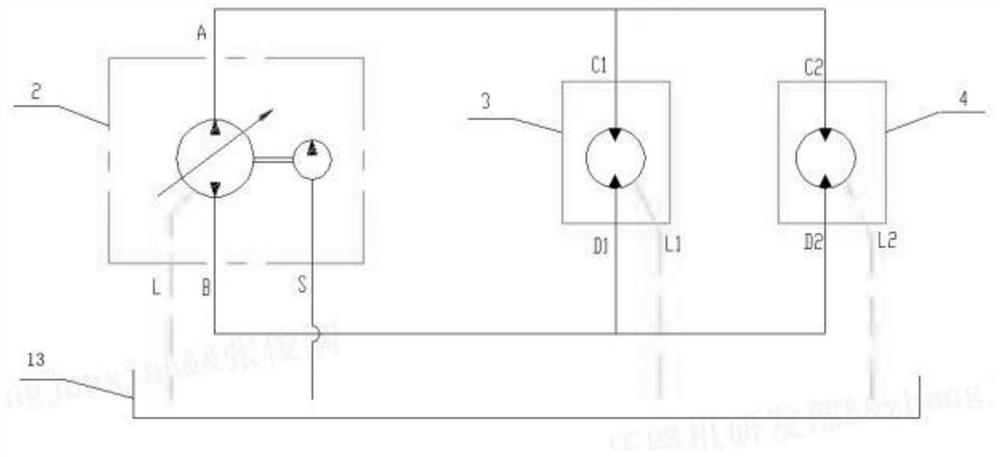
The invention discloses a novel hydraulic vibration system and a road roller. The vibration system comprises a hydraulic pump, a first hydraulic motor and a second hydraulic motor, wherein the workingend of the hydraulic pump is connected with the first hydraulic motor and the second hydraulic motor in parallel, the working end of the first hydraulic motor is connected with a first driving shaft,and the working end of the second hydraulic motor is connected with a second driving shaft; the first driving shaft is connected with a first vibration exciter, and the second driving shaft is connected with a second vibration exciter; the hydraulic pump works to drive the first driving shaft and the second driving shaft to rotate at the same time through the first hydraulic motor and the secondhydraulic motor, the first driving shaft drives the first vibration exciter to work, and the second driving shaft drives the second vibration exciter to work. The two hydraulic motors are connected inparallel, the pressure requirement of the system is low, and the service life of hydraulic system elements is relatively long.

Description

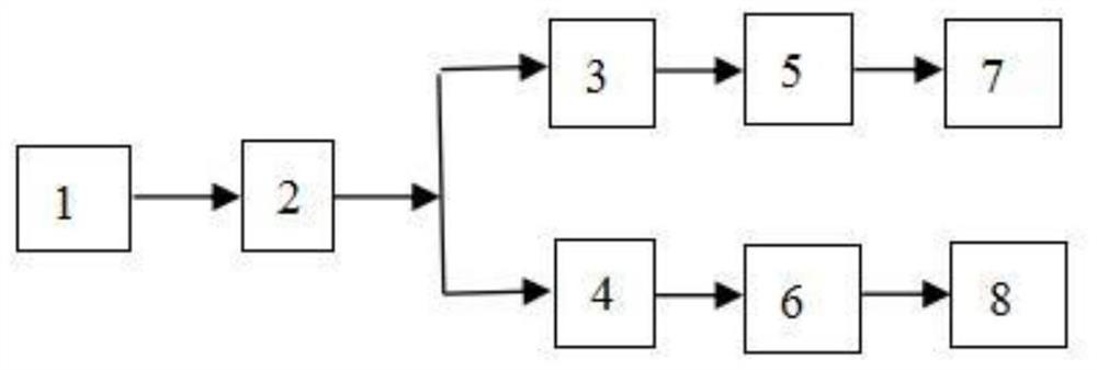
technical field [0001] The invention relates to the technical field of hydraulic systems, in particular to a novel hydraulic vibration system and a road roller. Background technique [0002] At present, the vibrating wheel with dual-axis drive (using the eccentric mechanism inside the vibrating wheel of the road roller driven by the dual-axis drive) in the industry is generally used to achieve vertical vibration or oscillation, and a single hydraulic motor is generally used to drive the drive shaft. Such as figure 1 As shown, the engine drives the high-pressure oil output by the hydraulic pump to enter the hydraulic motor, and the hydraulic motor transmits the power to the drive shaft of a vibrator. At the same time, the drive shaft is equipped with gears, and the power is transmitted synchronously and reversely to another exciter through gear meshing. The drive shaft of the exciter, so as to realize the synchronous direction rotation of the two exciters. [0003] Vertical...

Claims


Application Information

Patent Timeline
Patent Type & Authority Applications(China)
IPC IPC(8): E01C19/28
CPCE01C19/28E01C19/286
Inventor 周保刚张俊娴牛春亮郝鹿坤李韵玮
Owner XCMG CONSTR MACHINERY
Learn More