Anti-blocking spray head of continuous carbon fiber 3D printer
A 3D printer and carbon fiber technology, applied in coating devices, additive processing, etc., can solve problems such as inability to effectively dredge pipes, and achieve the effect of ensuring the dredging effect, easy operation, and fast dredging speed.
- Summary
- Abstract
- Description
- Claims
- Application Information
AI Technical Summary
Problems solved by technology
Method used
Image

Examples
specific Embodiment approach 1
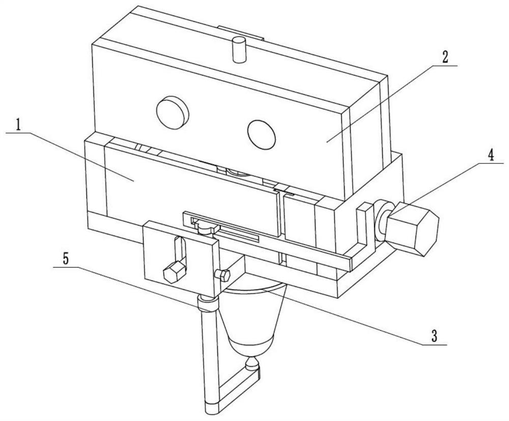
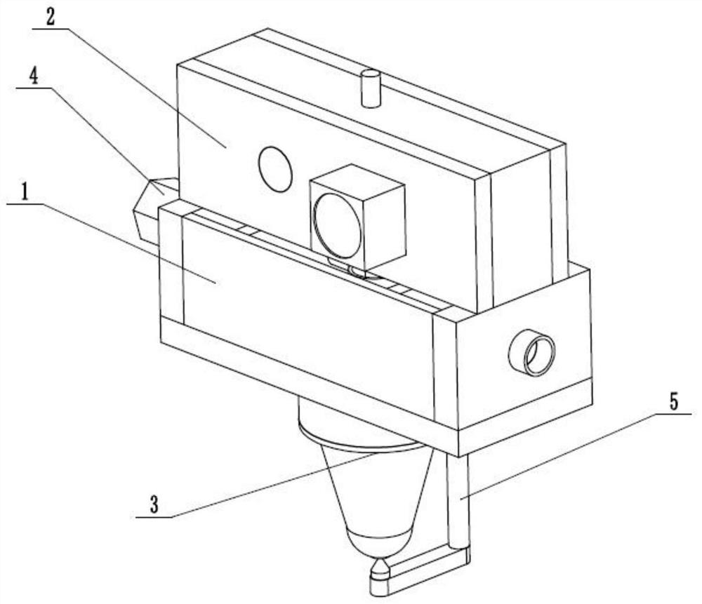
[0029] Such as Figure 1 to Figure 9 As shown, a continuous carbon fiber 3D printer anti-blocking nozzle includes an anti-blocking operation seat 1, a continuous adder 2, a heating nozzle 3, a regulator 4 and a combined anti-blocking dredge 5, and the continuous adder 2 is fixedly connected and Connected to the anti-blocking operation seat 1, the heating nozzle 3 is connected and connected to the lower end of the anti-blocking operation seat 1 through thread fit, the regulator 4 is rotatably connected in the anti-blocking operation seat 1, and the combined anti-blocking dredger 5 clearance fits in the adjustment In the device 4, the combined anti-block dredging device 5 is longitudinally slidably connected on the anti-block operating seat 1. 3D printing by melting filamentary carbon fiber is the core principle of 3D printers. After the printing is completed, the residual heat of the nozzle will melt the remaining raw materials in the nozzle, which will easily cause nozzle bloc...
specific Embodiment approach 2
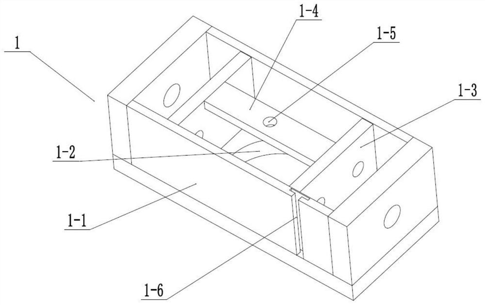
[0031] Such as Figure 1 to Figure 9As shown, this embodiment further explains Embodiment 1. The anti-blocking operation seat 1 includes a nozzle fixing frame 1-1, a nozzle connection screw hole 1-2, two supporting partitions 1-3, a connecting plate 1- 4. Filling connecting holes 1-5 and longitudinal T-shaped chute 1-6, the center of the lower end of the nozzle fixing frame 1-1 is provided with a nozzle connecting threaded hole 1-2, and two supporting partitions 1-3 are evenly fixed and connected on the In the nozzle fixing frame 1-1, the connection plate 1-4 is fixedly connected between the two supporting partitions 1-3, the filler communication hole 1-5 is set through the center of the connection plate 1-4, and the longitudinal T-shaped chute 1 -6 is arranged on the rear side of the outer wall of the nozzle fixing frame 1-1. The sliding position of the gear cylinder 4-10 under the connecting plate 1-4 is used to avoid deviation during the rotation.
specific Embodiment approach 3
[0033] Such as Figure 1 to Figure 9 As shown, this embodiment will further explain the second embodiment. The continuous feeder 2 includes a combination fixing seat 2-1, a filling hole 2-2, a filling motor fixing seat 2-3, a filling motor 2-4, a main Filler adding gear 2-5, right semi-circular groove ring 2-6, secondary filler adding gear 2-7, left semi-circular groove ring 2-8 and left fixed shaft 2-9, combined fixing seat 2-1 is fixedly connected to the nozzle fixing frame The upper end of 1-1, the stuffing hole 2-2 is set up and down on the combined fixing seat 2-1, the stuffing motor fixing seat 2-3 is fixedly connected to the combined fixing seat 2-1, and the stuffing motor 2-4 is fixedly connected to the stuffing On the motor fixing seat 2-3, the main filler adding gear 2-5 and the secondary filler adding gear 2-7 are all arranged in the combined fixing seat 2-1, and the main filler adding gear 2-5 is fixedly connected to the filler motor 2-4 On the transmission shaft,...
PUM
 Abstract
Description
Claims
Application Information
 - R&D
- Intellectual Property
- Life Sciences
- Materials
- Tech Scout
- Unparalleled Data Quality
- Higher Quality Content
- 60% Fewer Hallucinations
Browse by: Latest US Patents, China's latest patents, Technical Efficacy Thesaurus, Application Domain, Technology Topic, Popular Technical Reports.
© 2025 PatSnap. All rights reserved.Legal|Privacy policy|Modern Slavery Act Transparency Statement|Sitemap|About US| Contact US: help@patsnap.com