
Tea cleaning equipment

A technology for cleaning equipment and tea leaves, applied to lighting and heating equipment, tea treatment before extraction, cleaning methods and utensils, etc., can solve problems such as low efficiency and waste of time, and achieve the effect of reducing labor intensity and improving work efficiency

Inactive Publication Date: 2020-10-09
孟祥明
View PDF0 Cites 3 Cited by
  • Summary
  • Abstract
  • Description
  • Claims
  • Application Information

AI Technical Summary

Problems solved by technology

[0003] In our country, tea is deeply loved by the masses, and more and more people like to drink tea. In the process of tea production, it is often necessary to clean the new leaves that have just been picked, and now the tea is generally cleaned artificially. , and then spread out to dry, this method is inefficient and wastes time, so now there is an urgent need for a tea cleaning equipment that can both clean and dry the tea leaves

Method used


Image

  • Tea cleaning equipment
  • Tea cleaning equipment
  • Tea cleaning equipment

Examples


Embodiment 1

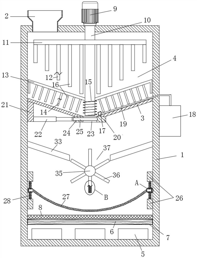
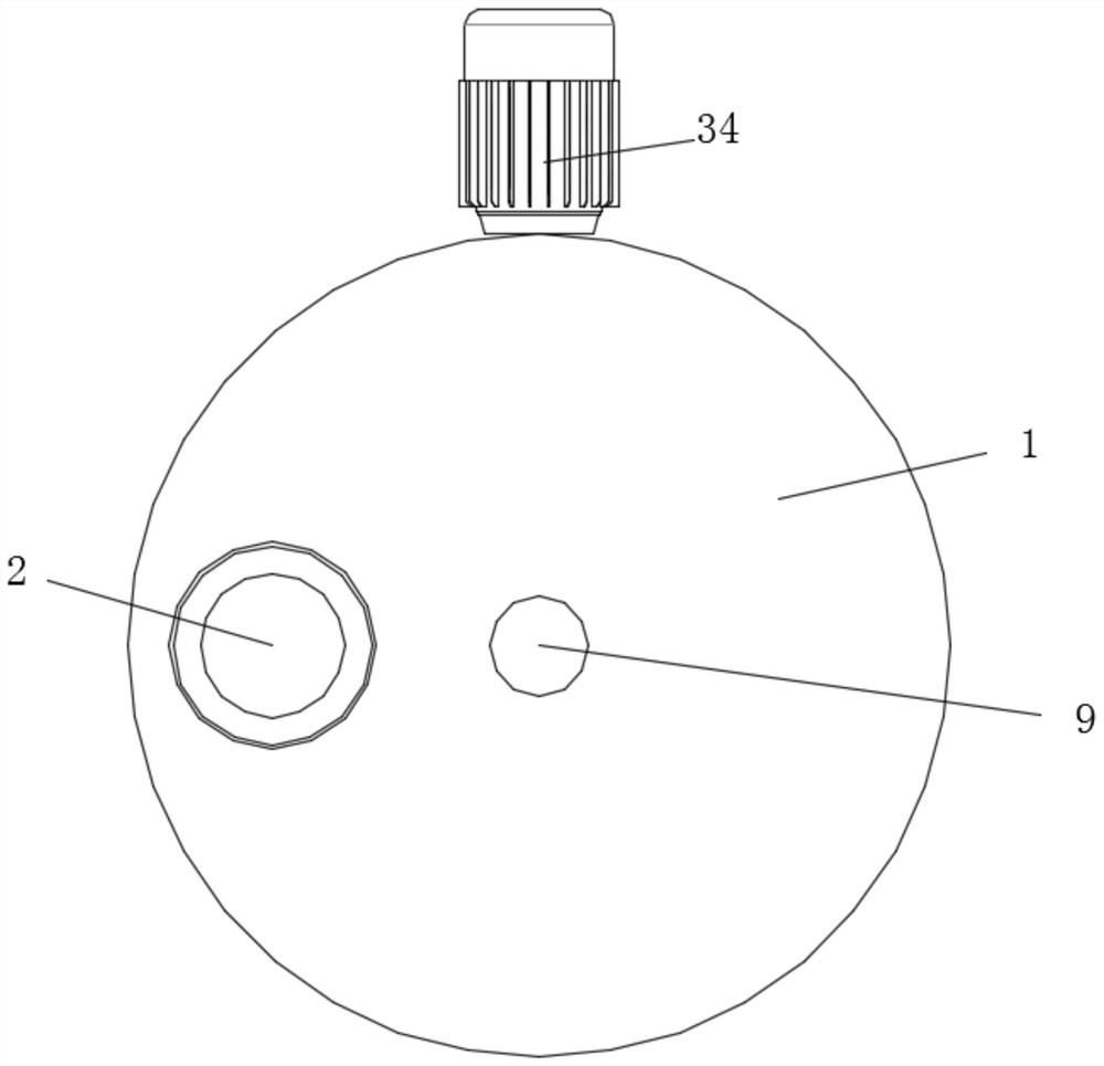
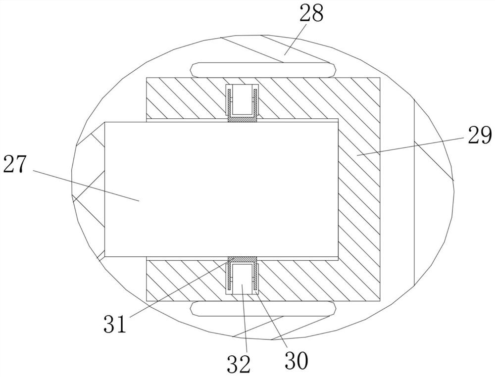
[0022] see Figure 1-4 , a kind of tea cleaning equipment, including a cleaning box 1, a feeding hopper 2 and a cleaning assembly, the feeding hopper 2 is arranged on the top of the cleaning box 1, and the cleaning assembly is arranged above the inside of the cleaning box 1, the The inner wall of the side of the cleaning box 1 is fixedly installed with a partition 3 formed integrally with it. The partition 3 is in the shape of a "V". The bottom of the partition 3 is provided with a dynamic sealing valve assembly. The partition 3 and the cleaning box 1 to form a cleaning chamber 4, a drainage assembly is arranged below the partition 3 in the cleaning chamber 4, a drying assembly is arranged at the bottom of the cleaning box 1, and a tea drying and placement assembly is arranged above the drying assembly The drying assembly includes a number of blowers 5 evenly arranged at the bottom of the cleaning box 1, a number of electric heating wires 6 above the blower 5, and an open inst...

Embodiment 2

[0030] This embodiment is further improved on the basis of the embodiment, and the improvement is that: a component blanking assembly is set between the tea storage grid trough 27 and the partition plate 3, and the side inner wall of the cleaning box 1 is fixedly installed and integrally formed with it The hollowed-out inclined-plane partition 33 in the middle, the component blanking assembly is located below the middle of the inclined-plane partition 33, and the component blanking assembly includes a component blanking motor 34 fixedly installed on the outer wall of the cleaning box 1, so The output end of the component blanking motor 34 is fixedly installed with a component blanking rotating shaft 35, and the component blanking rotating shaft 35 is rotatably installed on the cleaning box 1, and the component blanking rotating shaft 35 is evenly arranged with several component hollow partitions along the circumferential direction 36, a component groove 37 is formed adjacent to...


PUM


Abstract

The invention discloses tea cleaning equipment. The equipment comprises a cleaning box body, a feeding hopper and a cleaning assembly, a drying assembly is arranged at the bottom of the cleaning box body, a tea drying placement assembly is arranged above the drying assembly, the dry assembly comprises a plurality of fans, electric heating wires and a mounting frame, and a uniform heat dissipationnet is arranged above the mounting frame. According to the equipment, through the arrangement of the fans and the electric heating wires, tea is cleaned through the cleaning assembly, after drainage treatment of a drainage assembly, a power sealing valve assembly is opened, the tea to be dried falls on the tea drying placement assembly, the fans work to radiate heat generated by the electric heating wires, under the action of the uniform heat dissipation net, the air volume that emitted hot air blows to the tea drying placement assembly is uniform, and the uniform heat dissipation net can block a small amount of dripping moisture, so that the purpose of drying the tea is achieved, cleaning and drying of the tea are combined, labor intensity of workers is reduced, and work efficiency is improved.

Description

technical field [0001] The invention relates to the field of tea processing, in particular to tea cleaning equipment. Background technique [0002] Tea originated in China. Tea was first used as a sacrifice, but it has been used as a vegetable since the late Spring and Autumn Period. It was developed into a medicinal drink in the middle of the Western Han Dynasty, and it was developed into a high-grade court drink in the late Western Han Dynasty. It was popularized as a common drink by the people during the Western Jin Dynasty. Later, it was discovered that the earliest relic of artificial tea plantation was at the Tianluoshan site in Yuyao, Zhejiang Province, which has a history of more than 6,000 years. [0003] In our country, tea is deeply loved by the masses, and more and more people like to drink tea. In the process of tea production, it is often necessary to clean the new leaves that have just been picked, and now the tea is generally cleaned artificially. , and then...

Claims


Application Information

Patent Timeline
Patent Type & Authority Applications(China)
IPC IPC(8): B08B3/10B08B13/00F26B21/00F26B23/06F26B25/00A23F3/06
CPCA23F3/06B08B3/102B08B13/00F26B21/001F26B23/06F26B25/00
Inventor 孟祥明
Owner 孟祥明
Learn More