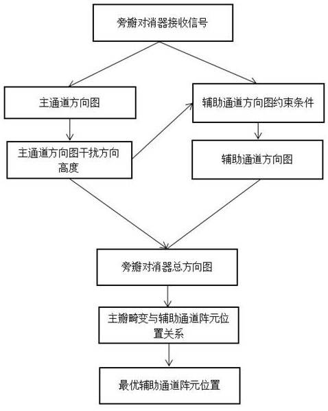
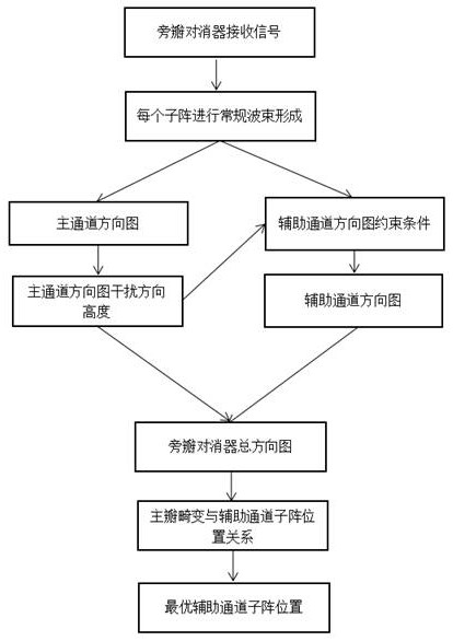
An Antenna Selection Method for Auxiliary Channel of Sidelobe Canceller Based on Beam Pattern
A beam pattern, auxiliary channel technology, applied in diversity/multi-antenna system, sustainable communication technology, radio transmission system, etc., can solve the problem of affecting the performance of side lobe canceller
- Summary
- Abstract
- Description
- Claims
- Application Information
AI Technical Summary
Problems solved by technology
Method used
Image
Examples
Embodiment 1
[0098] This embodiment exemplifies the correctness of the antenna selection method for the auxiliary channel of the sidelobe canceller based on the pattern with a single array element as the unit.
[0099] Using a uniform linear array of 16 antennas such as image 3 As shown, the position of the array element is half of the source wavelength, that is, is the unit, the expected signal incident angle is 0°, there are two interferences, the incident angles are 30° and 60° respectively, and 4 array elements are selected to form the auxiliary channel for sidelobe cancellation.
[0100] According to the method of the present invention, the selected auxiliary channel positions are obtained, i.e. positions 0, 1, 10, and 11, and these four position antennas are selected as the auxiliary channels to make the main channel, auxiliary channel, and sidelobe canceller direction diagrams respectively. Figure 4(a)-Figure 4(d). It can be seen from Figure 4(a)-Figure 4(d) that in the interfer...
Embodiment 2
[0103] This embodiment supplementally verifies the correctness of the antenna selection method for the auxiliary channel of the sidelobe canceller based on the pattern with a single array element as the unit.
[0104] Using a uniform linear array of 16 antennas such as Figure 5 As shown, the position of the array element is half of the source wavelength, that is, is the unit, the expected signal incident angle is 0°, there are three interferences, the incident angles are -60°, 30° and 60° respectively, and 6 array elements are selected to form the auxiliary channel for sidelobe cancellation.
[0105] According to the method of the present invention, the selected auxiliary channel positions are obtained, that is, positions 2, 4, 5, 10, 11, and 12, and these six position antennas are selected as the auxiliary channels to make the main channel, auxiliary channel, and side lobe cancellation respectively. The device direction diagram is shown in Figure 6(a)-Figure 6(d). It can ...
Embodiment 3
[0108] This embodiment verifies the correctness of the sub-array selection method based on the pattern of the sidelobe canceller auxiliary channel with the sub-array as the unit.
[0109] Using 8 sub-arrays, each sub-array is a uniform linear array composed of three array elements, such as Figure 7 As shown, the position of the array element is half of the source wavelength, that is, is the unit, the expected signal incident angle is 0°, there are two interferences, the incident angles are 30° and 60° respectively, and three sub-arrays are selected to form auxiliary channels for sidelobe cancellation.
[0110] According to the method of the present invention, the selected auxiliary channel sub-array positions are obtained, i.e. positions 0, 5, and 7, and these three position sub-arrays are selected as auxiliary channels to make the main channel, auxiliary channel, and side lobe canceller direction diagram respectively As shown in Figure 8(a)-Figure 8(d). It can be seen fro...
PUM
 Abstract
Description
Claims
Application Information
 - Generate Ideas
- Intellectual Property
- Life Sciences
- Materials
- Tech Scout
- Unparalleled Data Quality
- Higher Quality Content
- 60% Fewer Hallucinations
Browse by: Latest US Patents, China's latest patents, Technical Efficacy Thesaurus, Application Domain, Technology Topic, Popular Technical Reports.
© 2025 PatSnap. All rights reserved.Legal|Privacy policy|Modern Slavery Act Transparency Statement|Sitemap|About US| Contact US: help@patsnap.com


