
Multi-power supply control method, device and equipment and multi-power supply system

A power supply and power supply control technology, applied in circuit devices, emergency power supply arrangements, parallel operation of DC power supplies, etc., can solve the problems of low power supply load rate, power waste, low power supply efficiency, etc., and achieve the effect of improving stability.

Inactive Publication Date: 2020-10-02
RUIJIE NETWORKS CO LTD
View PDF3 Cites 3 Cited by
  • Summary
  • Abstract
  • Description
  • Claims
  • Application Information

AI Technical Summary

Problems solved by technology

[0004] However, in many scenarios, there are situations where the equipment is not fully configured. For example, only 1 or 2 equipment may work. From the perspective of equipment reliability, the power supply will not be reduced. At this time, if the N+N power supply is fully configured, it may actually only need 1 or 2 equipment. A single power supply can meet the power supply demand, which will lead to a small load rate of the power supply, resulting in low power supply efficiency and serious waste of electric energy.
[0005] In order to ensure the high reliability of the equipment and the stability of the power supply, multiple power supplies are required to work redundantly, but this design will cause serious waste of electric energy. It is necessary to provide a design scheme that can ensure the stability of the power supply and save energy.

Method used


Image

  • Multi-power supply control method, device and equipment and multi-power supply system
  • Multi-power supply control method, device and equipment and multi-power supply system
  • Multi-power supply control method, device and equipment and multi-power supply system

Examples


Embodiment Construction

[0075] In order to make the purpose, technical solution and advantages of the application clearer, the application will be further described in detail below in conjunction with the accompanying drawings. Apparently, the described embodiments are only some of the embodiments of the application, not all of them. Based on the embodiments in this application, all other embodiments obtained by persons of ordinary skill in the art without making creative efforts belong to the scope of protection of this application.

[0076] Part of the terms used in the embodiments of the present application are explained below to facilitate the understanding of those skilled in the art.

[0077] (1) Rack-mounted switch: Rack-mounted switch belongs to a category of switches. It is a slot-type switch that can be installed in a standard 19-inch cabinet. It is beautiful in appearance and has good scalability. , can support different network types, such as Ethernet, Fast Ethernet, Gigabit Ethernet, ATM...


PUM


Abstract

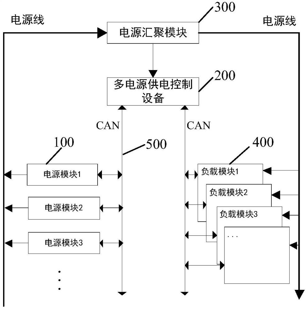
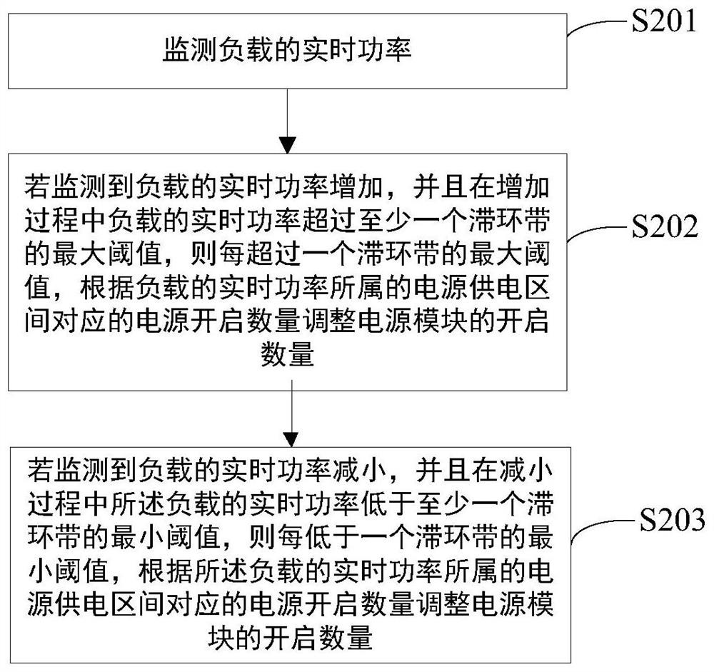
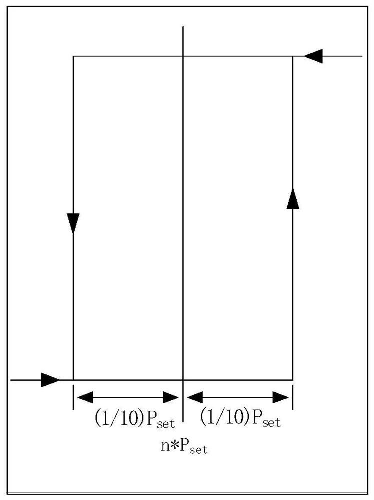
The invention provides a multi-power supply control method, device and equipment and a multi-power supply system. The method comprises the steps that the real-time power of a load is monitored; if thereal-time power is monitored to be increased and the maximum threshold value of at least one hysteresis band is exceeded in the increasing process, the opening number of the power modules is adjustedaccording to the power supply opening number corresponding to the power supply interval to which the real-time power of the load belongs every time the maximum threshold value of one hysteresis bandis exceeded; and if the real-time power is monitored to be reduced and the real-time power of the load is lower than the minimum threshold value of at least one hysteresis band in the reduction process, the opening number of the power supply modules is adjusted according to the power supply opening number corresponding to the power supply interval to which the real-time power of the load belongs every time the real-time power is lower than the minimum threshold value of one hysteresis band. According to the method, the hysteresis band is arranged, so that frequent opening and closing of a certain power supply module possibly caused under the condition that the power fluctuates within a certain range are avoided, and the stability of the system can be effectively improved.

Description

technical field [0001] The present invention relates to the technical field of multi-power supply control technology, in particular to a multi-power supply control method, device, equipment and multi-power supply system. Background technique [0002] With the continuous development of communication technology and continuous upgrading of communication equipment, the amount of data carried by communication equipment has become larger and larger, and the power consumption has also become larger and larger. Nowadays, "green" and "energy saving" are the pursuit direction of various products in the information age, especially high power consumption products, such as switches and servers. [0003] For some high power consumption products, multiple power supplies may be equipped because of the huge amount of data involved and the high power consumption requirements of the whole machine. Common multi-power supply configurations are N+1, N+M, and N+N redundancy (here N refers to the ...

Claims


Application Information

Patent Timeline
IPC IPC(8): H02J13/00H02J9/06H02J1/10
CPCH02J1/10H02J9/061H02J13/00001H02J13/00016Y02B90/20Y04S20/12
Inventor 杜伟煌
Owner RUIJIE NETWORKS CO LTD
Learn More