
Beer outlet valve of beer machine

A technology of beer machine and wine outlet, which is applied in the direction of lift valve, valve details, valve device, etc., can solve the problems of long purging time, cumbersome two independent purging, affecting the taste, etc., and achieves efficient purging or cleaning. Purge efficiency with no residue, control or ease of operation effects

Pending Publication Date: 2020-10-02
宁波鲜啤三十公里科技有限公司
View PDF2 Cites 2 Cited by
  • Summary
  • Abstract
  • Description
  • Claims
  • Application Information

AI Technical Summary

Problems solved by technology

However, since this type of wine outlet valve has a spring that has been in contact with the wine liquid for a long time, the overall structure is also relatively complicated; There is a problem of odor in the process of flowing out of the wine through the outlet valve
[0004] In this regard, some people propose to use gas to purge the wine outlet valve after each wine out. However, first of all, regardless of the working state of the wine outlet valve for purging, the gas cannot pass through the spring. The area where the spring is located, in this way, will directly lead to the area where the spring is located will become a sanitary corner of the wine valve. After long-term use, it will not only bring about odor and affect the taste, but also seriously affect the hygiene of the wine valve.
[0005] Secondly, the wine outlet channel and the foam outlet channel of this type of wine outlet valve are two different channels. If it is purged in the state of wine outlet, the cleanliness of the foam channel cannot be guaranteed; if it is purged in the state of foam outlet , it is impossible to guarantee the cleanliness of the channel through which the wine flows; When the control method is complicated
[0006] Moreover, even if the two states of the wine outlet valve are cumbersomely purged twice with the help of gas after each wine outlet, it still cannot solve the problem that the above-mentioned area where the middle spring is located will inevitably become a dead corner of the wine outlet valve.

Method used


Image

  • Beer outlet valve of beer machine
  • Beer outlet valve of beer machine
  • Beer outlet valve of beer machine

Examples


Embodiment Construction

[0043] In order to clearly illustrate the technical characteristics of this patent, the following describes this patent in detail through specific implementation methods and in conjunction with the accompanying drawings.

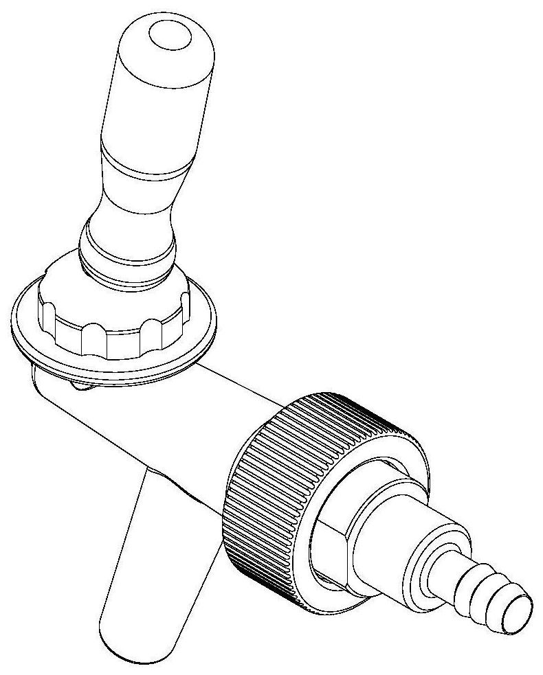
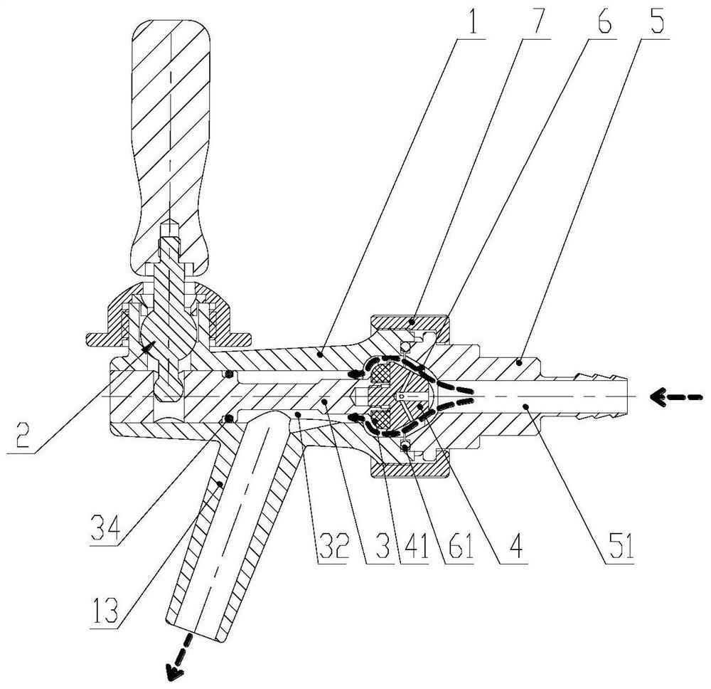
[0044] The present invention as Figure 1-6 As shown, it includes a valve body 1, a lever 2 and a valve stem 3. The valve body 1 is provided with a valve stem hole 11 adapted to the valve stem 3, and an operating hole 12 is provided on the side wall of the valve body 1. , the bottom of the valve body 1 is provided with a wine outlet pipe 13 communicating with the valve stem hole 11, and the side wall of the valve stem 3 is provided with a flow passage 32 communicating with the wine outlet pipe 13, and the valve stem 3 is slidably arranged in the valve stem hole 11, and the valve stem 3 is provided with a driving hole 31 for accommodating the driving rod 2, the driving rod 2 is hinged with the valve body 1, and the driving rod 2 passes through the The operat...


PUM


Abstract

The invention discloses a beer outlet valve of a beer machine, and relates to the field of liquid filling equipment. The beer outlet valve of the beer machine is simple in structure, convenient to useand good in user experience, and can keep long-acting cleanness and sanitation through quick and efficient single cleaning. The beer outlet valve comprises a valve body 1, a poking rod 2 and a valverod 3, wherein a valve rod hole 11 matched with the valve rod 3 is formed in the valve body 1; a beer outlet pipe 13 communicating with the valve rod hole 11 is arranged at the bottom of the valve body 1; a flowing channel 32 is formed in the side wall of the valve rod 3; and the poking rod 2 is poked to drive the valve rod 3 to perform a reciprocating motion in the valve rod hole 11. The beer outlet valve further comprises a valve base 5 fixedly connected to one side of the valve body 1; an accommodating space 6 is formed between the valve rod hole 11 and an inlet hole 51; a valve element 4 fixedly connected with the valve rod 3 is arranged in the accommodating space 6; and a bubble exciting channel is formed in the valve element 4. The beer outlet valve prevents the problems of flavor mixing and influence on the taste, and can keep long-acting cleanness and sanitation.

Description

technical field [0001] The invention relates to the field of liquid filling equipment, in particular to an improvement of a wine outlet valve of a beer vending machine. Background technique [0002] At present, most of the existing beer machine outlet valves (or wine outlet taps) are like the "Beverage Injection Cock Valve, Valve Stem and Beverage Dispenser" published by the National Bureau on July 30, 2019. As shown in the Chinese invention patent application with the number "201680091507.X", or as shown in a Chinese utility model patent named "Dragon Head" with the application number "201020553247.3" announced by the National Bureau on July 27, 2011. During the use of this type of wine valve, when the valve stem is turned to the front position, the purpose of wine can be achieved, and when the valve stem is turned to the back position, the purpose of foam can be achieved. Under normal conditions, the valve stem is in the middle position , at this time the wine outlet valv...

Claims


Application Information

Patent Timeline
Patent Type & Authority Applications(China)
IPC IPC(8): F16K1/38F16K31/60B67D1/07B67D1/12
CPCB67D1/07B67D1/12B67D2001/0093F16K1/38F16K31/60
Inventor 黄粤宁陈明
Owner 宁波鲜啤三十公里科技有限公司
Learn More