Transfer printing component feeding machine
A component and feeder technology, applied in the field of pad printing component feeder, can solve the problems of frequent operation and achieve the effect of reducing manual operation
- Summary
- Abstract
- Description
- Claims
- Application Information
AI Technical Summary
Problems solved by technology
Method used
Image

Examples
Embodiment 1
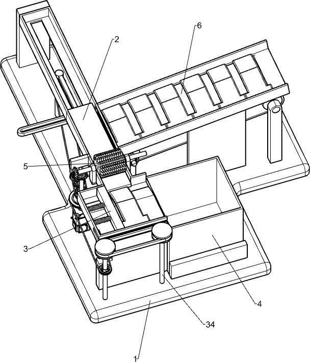
[0038] A feeding machine for pad printing parts, such as figure 1 As shown, it includes a base 1, a pushing mechanism 2 and a feeding mechanism 3. The pushing mechanism 2 is installed on the left side of the base 1, and the feeding mechanism 3 is installed on the left front side of the base 1. The feeding mechanism 3 is connected with the pushing mechanism 2. .
[0039] When it is necessary to print a certain object in large quantities, first place the device next to the pad printing machine, so that the parts in the pushing mechanism 2 are located directly below the printing part of the pad printing machine, and then place an object to be printed Place it in the parts of the pushing mechanism 2 so that it is located on the front side of the pushing parts of the pushing mechanism 2, start the parts in the pushing mechanism 2, and the parts in the pushing mechanism 2 will rotate clockwise accordingly, and the inside of the pushing mechanism 2 The rotation of the parts drives t...
Embodiment 2
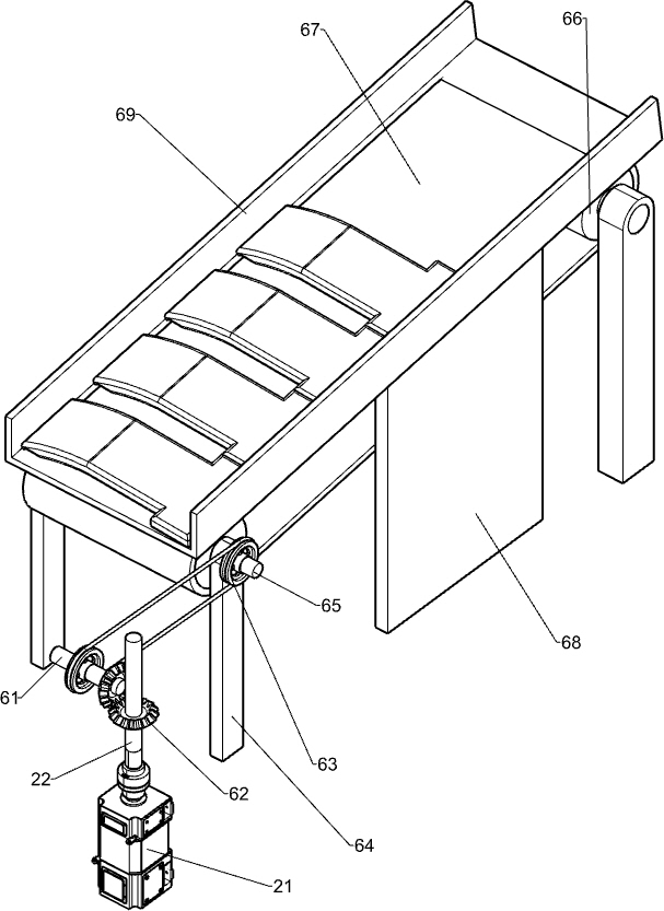
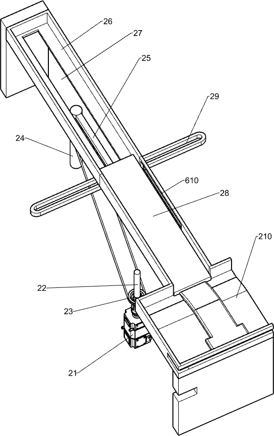
[0041] Specifically, such as Figure 1-3As shown, the pushing mechanism 2 includes a motor 21, a transmission shaft 22, a first belt assembly 23, a first rotating shaft 24, a rotating rod 25, a slide rail 26, a push plate 28, a guide rail 29 and a workbench 210, and the left front side of the base 1 is installed There is a motor 21, the output shaft of the motor 21 is connected with a transmission shaft 22, the left rear part of the base 1 is rotatably provided with a first rotating shaft 24, and a first belt assembly 23 is connected between the upper part of the first rotating shaft 24 and the lower part of the transmission shaft 22 , the top of the first rotating shaft 24 is equipped with a rotating rod 25, a slide rail 26 is installed on the left side of the base 1, and a strip hole 27 is provided on the slide rail 26, and a push plate 28 is slidably installed in the strip hole 27. The rear side of the bottom of 28 is provided with a guide rail 29, the front end of the rota...
Embodiment 3
[0046] refer to figure 1 and Figure 4-5 , also includes a collection frame 4, the front side of the base 1 is slidingly provided with the collection frame 4, and the collection frame 4 is located on the right side of the workbench 210.
[0047] The push block 38 drives the printed object to move to the right. When the printed object is out of contact with the workbench 210, the printed object falls into the collection frame 4. After the collection frame 4 is filled with objects, it moves to the right. Take it out, pour the contents inside it into the collection bag, move the collection frame 4 to the left and put it back to collect the printed articles again.
[0048] Also comprise cleaning mechanism 5, and cleaning mechanism 5 comprises the 3rd rotating shaft 51, the first bevel gear 52 and cylindrical hairbrush 53, and the rotation type is provided with the 3rd rotating shaft 51 between the left and right parts of slide rail 26 front sides, and the 3rd rotating shaft A fi...
PUM
 Abstract
Description
Claims
Application Information
 - R&D
- Intellectual Property
- Life Sciences
- Materials
- Tech Scout
- Unparalleled Data Quality
- Higher Quality Content
- 60% Fewer Hallucinations
Browse by: Latest US Patents, China's latest patents, Technical Efficacy Thesaurus, Application Domain, Technology Topic, Popular Technical Reports.
© 2025 PatSnap. All rights reserved.Legal|Privacy policy|Modern Slavery Act Transparency Statement|Sitemap|About US| Contact US: help@patsnap.com