Automobile swing arm with reinforced buffering anti-collision structure
A car swing arm and anti-collision technology, which is applied to the cantilever mounted on the pivot, vehicle components, suspension, etc., can solve the problems of inconvenient installation of the front bush, poor versatility of the lower swing arm, and affecting the use of the lower swing arm. , to achieve the effect of improving connection stability, prolonging service life and improving strength
- Summary
- Abstract
- Description
- Claims
- Application Information
AI Technical Summary
Problems solved by technology
Method used
Image
Examples
Embodiment 1
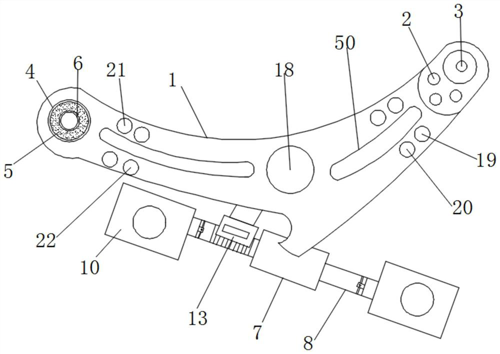
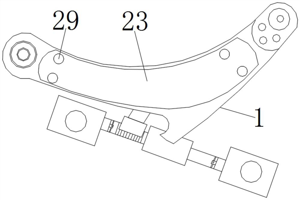
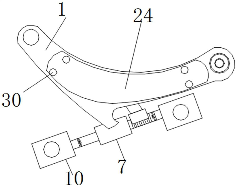
[0038] see Figure 1-12 , according to an embodiment of the present invention, a car swing arm with a reinforced buffer and anti-collision structure includes a swing arm body 1, and a reinforcing rib 50 is provided on the surface of the swing arm body 1, and the reinforcing rib 50 is used to improve the swing arm body 1. The strength of the swing arm body 1 reduces the possibility of bending. The surface of the swing arm body 1 is coated with an anti-corrosion coating. The anti-corrosion coating can improve the corrosion resistance of the swing arm body 1. One end of the swing arm body 1 is connected to Part 2 is fixedly connected with a ball stud assembly 3, and the other end of the swing arm body 1 is provided with a rear bush assembly, which includes a rear bush outer frame 4, a rubber body 5 and a rear bush A sleeve inner frame 6, the inside of the swing arm body 1 is provided with a rear bush outer frame 4, and the rear bush outer frame is connected to the rear bush inner...
Embodiment 2
[0044] see Figure 6 , the moving mechanism includes a moving rod 31, a socket three 32 and an arc-shaped plate three 33, and the side of the arc-shaped plate two 15 away from the connecting rod 8 is fixedly connected with a moving rod 31, and the inside of the cavity 14 A socket three 32 is opened near the moving rod 31, and the end of the moving rod 31 away from the arc plate two 15 passes through the three sockets 32 and is located outside the three sockets 32. One end of the rod 31 located outside the socket three 32 is connected to the arc plate three 33, and a spring one 34 is connected between the cavity 14 and the two arc plate 15, and the spring one 34 is wound around the Describe the outer surface of the moving rod 31, the moving mechanism is convenient for the operation of moving the arc plate two 15, so that the connecting rod 8 can be adjusted to the arc plate one 13, and the spring one 34 plays the role of pushing the arc plate two 15 , when the side wall of the...
Embodiment 3
[0046] see Figure 7-11 , the limiting mechanism includes a connecting block 2 35, a limiting ring 36, a socket 4 37 and a limiting rod 38, and the end of the mounting sleeve 9 away from the mounting block 10 is fixedly connected with the connecting block 2 35, the The inner side of the connecting block 35 is provided with an arc surface matched with the connecting rod 8, and the arc surface is adapted to the outer wall of the connecting rod 8 to facilitate the rotating operation of the connecting block 2 35 around the connecting rod 8. The connecting block 2 35 There is a socket 4 37 on the surface of the socket 4 37, and the inside of the socket 4 37 is provided with a limit rod 38, and the connecting rod 8 opens a limit ring 36 close to the limit rod 38, and one end of the limit rod 38 is located at In the limiting ring 36, the other end of the limiting rod 38 is connected with the connecting mechanism;
[0047] As for the connecting mechanism, it should be noted that the ...
PUM
 Abstract
Description
Claims
Application Information
 - R&D
- Intellectual Property
- Life Sciences
- Materials
- Tech Scout
- Unparalleled Data Quality
- Higher Quality Content
- 60% Fewer Hallucinations
Browse by: Latest US Patents, China's latest patents, Technical Efficacy Thesaurus, Application Domain, Technology Topic, Popular Technical Reports.
© 2025 PatSnap. All rights reserved.Legal|Privacy policy|Modern Slavery Act Transparency Statement|Sitemap|About US| Contact US: help@patsnap.com


