
Dewatering equipment for foamed plastic

A technology of foam plastics and equipment, which is applied in the field of foam plastics, and can solve problems such as clogged drainage holes, foam detachment, and affecting water removal from foam plastics

Pending Publication Date: 2020-10-02
菏泽岸绿装饰有限公司
View PDF0 Cites 0 Cited by
  • Summary
  • Abstract
  • Description
  • Claims
  • Application Information

AI Technical Summary

Problems solved by technology

[0003] At present, there is a kind of water removal equipment for foamed plastics, and when the foamed plastics are dewatered, the foamed plastics are added into the centrifugal cylinder, and then the centrifugal force in the centrifugal cylinder drives the foam under the high-speed rotation of the centrifugal cylinder. The plastic rotates, but when the foam plastic rotates, its outer side will rub against the inner wall of the centrifuge cylinder, causing part of the foam to break away from the friction, and drill into the drain hole of the centrifuge cylinder under the action of centrifugal force, causing the clogging of the drain hole to affect the centrifuge cylinder's effect on the foam. dehydration of plastic

Method used


Image

  • Dewatering equipment for foamed plastic
  • Dewatering equipment for foamed plastic
  • Dewatering equipment for foamed plastic

Examples


Embodiment 1

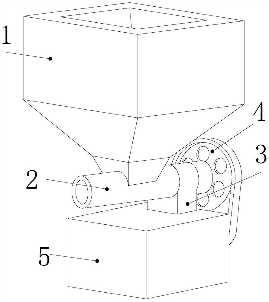
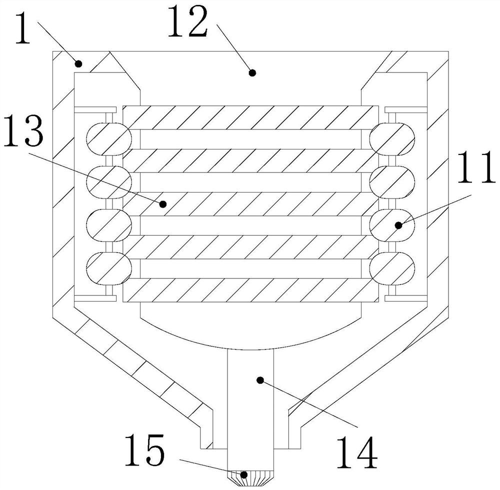
[0029] The invention provides a water removal device for foamed plastics. Its structure includes a feed port 1, a discharge pipe 2, a support platform 3, a rotating block 4, and a machine base 5. The bottom of the feed port 1 is embedded in the discharge pipe. 2, the discharge pipe 2 is welded on the upper surface of the support platform 3, the bottom of the support platform 3 is welded to the top of the machine base 5, the rotary block 4 is mounted on the back of the discharge pipe 2, and the feeding port 1 It includes a positioning block 11, a centrifugal cylinder 12, a clamping plate 13, a rotating rod 14, and teeth 15. The outside of the positioning block 11 is embedded in the inner wall of the feeding port 1, and the centrifugal cylinder 12 is installed inside the feeding port 1. The card The plate 13 is welded on the outer surface of the centrifugal cylinder 12 and engages with the positioning block 11. The top of the rotating rod 14 is welded on the bottom of the centrif...

Embodiment 2

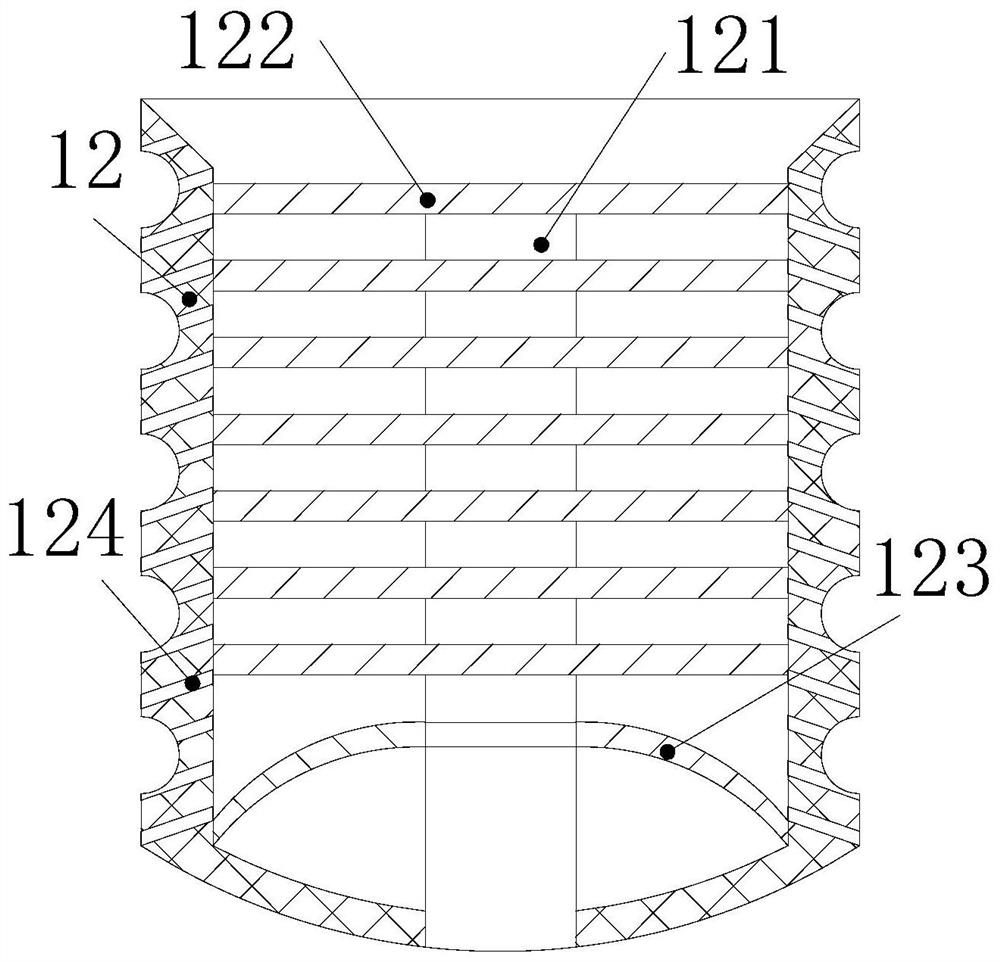
[0036] In the figure, the centrifugal cylinder 12 includes a rotating shaft 121, a rotating plate 122, a sealing plate 123, and a drainage hole 124. The rotating shaft 121 and the centrifugal cylinder 12 are located on the same axis, and the rotating plate 122 is embedded on the outside of the rotating shaft 121 and passed The gap is connected to the inner wall of the centrifugal cylinder 12, the inner side of the sealing plate 123 is close to the outer surface of the rotating shaft 121, and the outer side of the sealing plate 123 is welded on the inner wall of the centrifugal cylinder 12, the drainage hole 124 runs through the inner wall of the centrifugal cylinder 12, and the sealing plate 123 is made of rubber and the inner side is higher than the outer side, and the drainage hole 124 is inclined, and the outer side of the drainage hole 124 is downward, which is beneficial to throwing out the moisture in the foam plastic under the rotation of the centrifugal cylinder 12 and d...


PUM


Abstract

The invention discloses dewatering equipment for foamed plastics. The dewatering equipment structurally comprises a feeding port, a discharging pipe, a supporting table, a rotating block and a machinebase, the bottom of the feeding port is embedded and fixed to the upper portion of the discharging pipe, the discharging pipe is welded to the upper surface of the supporting table, the bottom of thesupporting table is welded to the top of the machine base, and the rotating block is installed on the back of the discharging pipe in a matched mode. The dewatering equipment has the following beneficial effects that foamed plastic is placed in a storage groove, and a motor is started to enable a centrifugal cylinder to rotate to generate centrifugal force to drive the foamed plastic in the storage groove to rotate around a rotating shaft, so that water in the foamed plastic is thrown out, and a gap is formed between the foamed plastic and the inner wall of the centrifugal cylinder through the storage groove; and foamed plastic is prevented from being abraded in the dewatering process to cause part of the foamed plastic to fall off and block drainage holes to affect dewatering of the foamed plastic by the centrifugal cylinder, the inclined drainage holes enable water thrown out through the centrifugal cylinder to flow outwards, and the water is prevented from being accumulated in thecentrifugal cylinder and flowing back into the foamed plastic.

Description

technical field [0001] The invention relates to the field of foamed plastics, in particular to a water removal device for foamed plastics. Background technique [0002] Foam plastics, also known as microporous plastics, are widely used in our lives because of their light weight, heat insulation, sound absorption, and shock absorption. Before foam plastics are granulated, they need to be cleaned, because the foam after cleaning Plastic absorbs a lot of moisture because the moisture needs to be removed from the foam to make the foam lightweight. [0003] At present, there is a kind of water removal equipment for foamed plastics, and when the foamed plastics are dewatered, the foamed plastics are added to the centrifugal cylinder, and then the centrifugal force in the centrifugal cylinder drives the foam under the high-speed rotation of the centrifugal cylinder. The plastic rotates, but when the foam plastic rotates, its outer side will rub against the inner wall of the centri...

Claims


Application Information

Patent Timeline
Patent Type & Authority Applications(China)
IPC IPC(8): B29C37/00
CPCB29C37/0092
Inventor 吴惠章
Owner 菏泽岸绿装饰有限公司
Learn More